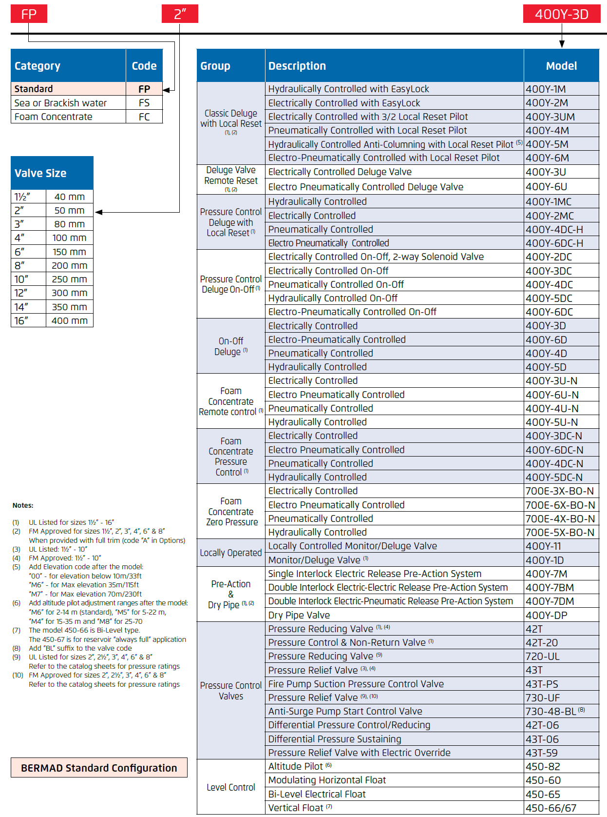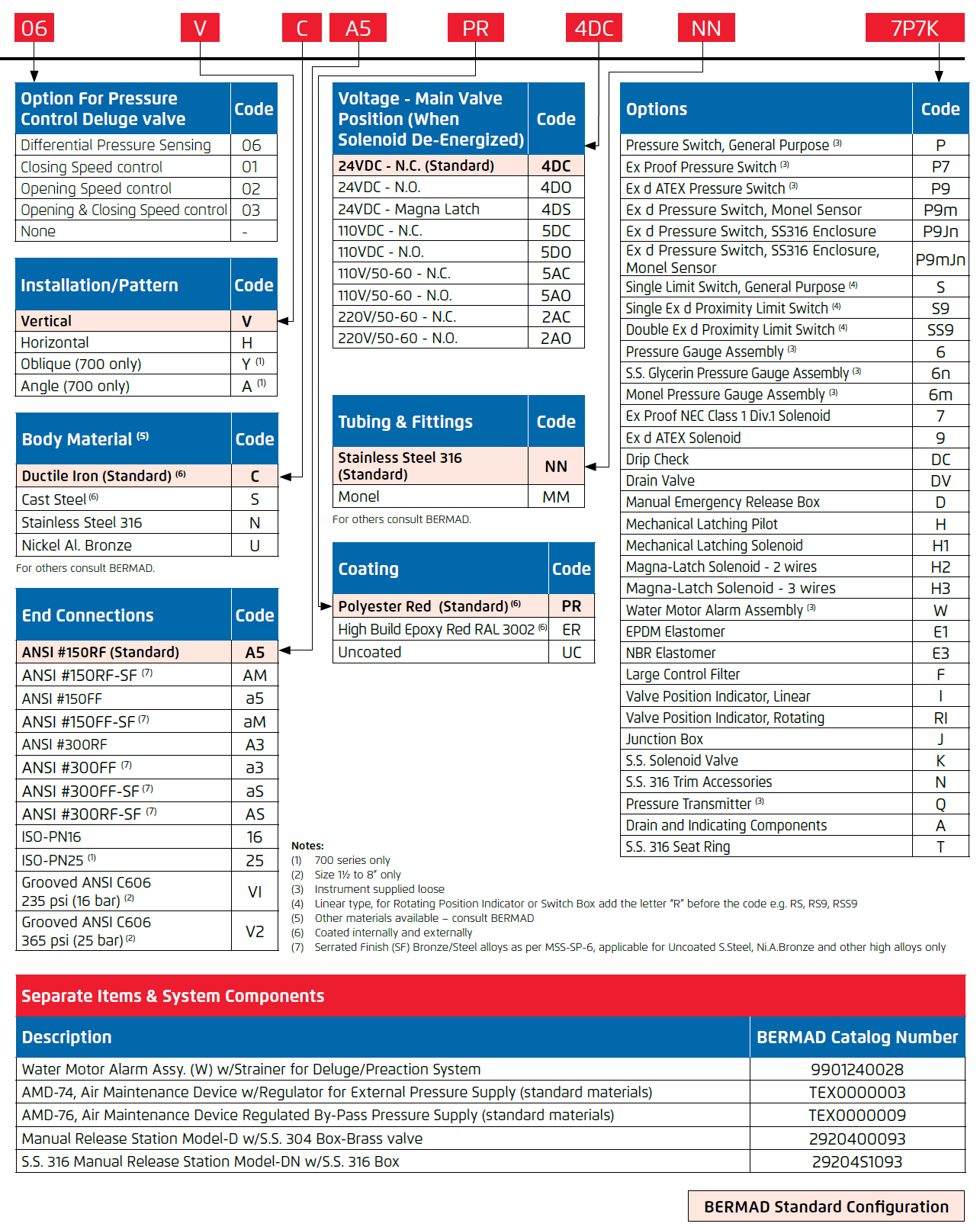
| Brand: | Bermad |
| Category: | Control Valves, Fire Protection Series |
| Size Range: | 40-400mm |
| Connection: | 40-400mm - Flanged 40-200mm - Grooved |
| Engineering Data: |
Product Description
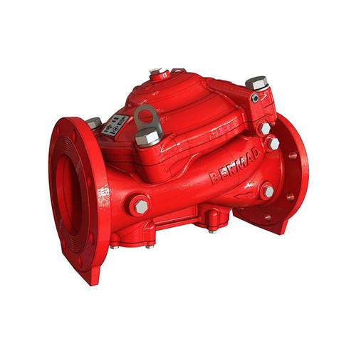
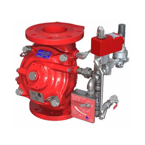
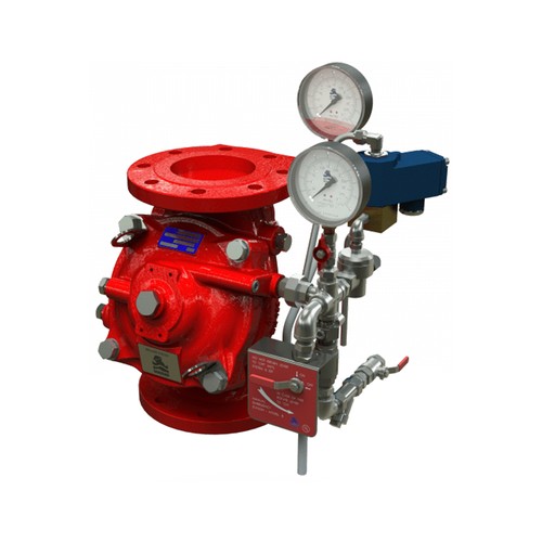
The BERMAD model 400Y-3D is an elastomeric, hydraulic line pressure-operated deluge valve, designed specifically for advanced fire protection systems, and the latest industry standards. The 400Y-3D is activated by a 3-way solenoid valve, suitable for electric fire detection systems. The optional valve position indicator can include a limit switch suitable for Fire & Gas monitoring systems. The 400Y-3D is ideal for systems with open nozzles for water or foam discharge. Available with electric components to suit any hazardous location.
Features and Benefits
- Safety and reliability
- Time-proven, Simple, fail-safe actuation
- Single-piece, rugged elastomeric diaphragm seal - VRSD technology
- An obstacle-free, uninterrupted flow path
- No mechanical moving parts
- Shuts off on remote command
- High performance
- Very high flow efficiency
- Approved for PN25 / 365 psi
- Straight through flow Y-type body
- Specifically designed for fire protection
- Face-to-face length standardized to ISO 5752, EN 558-1
- Meets the requirements of industry standards
- Quick and easy maintenance
- In-line serviceable
- Fast and easy cover removal
- Swivel-mounted drain valves*
* not including 1½” & 2” valves
Approvals

Additional Features
- Valve position limit switches
- Local valve position indicator beacon
- Sea water compatibility
- Alarm pressure switch
- Drain valve/s inlet/outlet
- For “automatic activation” select BERMAD local or remote reset model
Typical Applications
- Electric fire detection systems with control panels
- Remote control water spray systems
- Foam applications
- Corrosive water supplies
Technical Data
Operation

The BERMAD model 400Y-3D is held closed by water pressure in the control chamber [1]. Upon release of pressure from the control chamber, the valve opens. Under NORMAL conditions, water pressure is supplied to the control chamber via the priming line [2], restriction orifice [5] and strainer [3], and is then trapped in the control chamber by a check valve [4], manual emergency release [6], and a relay valve (HRV) [7] that is held closed by hydraulic pressure supplied through a three-way solenoid valve [8]. The water pressure trapped in the main valve control chamber holds the diaphragm against the valve seat, sealing it drip-tight and keeping the system pipes dry. Under FIRE conditions, water pressure is released from the control chamber, either with the manual emergency release or by the HRV opening in response to the solenoid valve being activated by the fire & gas control system [C]. This opens the 400Y-3D deluge valve, allowing water to flow into the system piping.
System P&ID

Components
1 BERMAD 400Y Deluge Valve
2 Priming Ball Valve
3 Priming Strainer
4 Check valve
5 Restriction Orifice
6 Manual Emergency Release
7 HRV-Hydraulic Relay Valve
8 3-Way NC Solenoid Valve
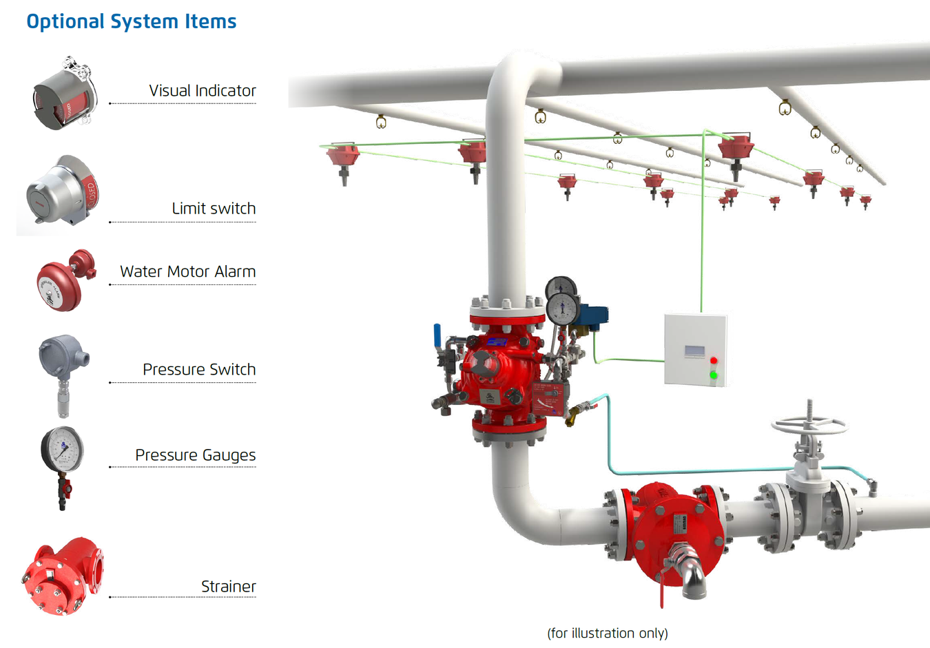
Optional System Items
ZS Limit Switch Assembly
I Visual Indicator
DC Automatic Drip Check Valve*
DV Additional Drain Valve
PI Pressure Indicator*
PS Pressure Switch
W Water Motor Alarm
9 3-Way Alarm Valve*
10 Drain Valve*
* Included in code suffix A “Drain and Indicating Components”.
Main Valve
Available Sizes and Connection
- 40-400mm - Flanged
- 40-200mm - Grooved
Pressure Rating
- ANSI#150 - 16 bar / 235 psi
- ANSI#300 -1½” to 10” 25 bar / 365 psi
12” to 16” 20 bar / 300 psi - Grooved/Threaded - 25 bar / 365 psi
Elastomer
- HTNR - Fabric Reinforced High Temperature
System Installation
A typical installation of the BERMAD model 400Y-3D features actuation via a hydraulic relay valve and three-way solenoid valve, triggered by a signal from a fire & gas control system or an on-site emergency pushbutton. When open and fitted with a limit switch the valve can send a feedback signal to a remote valve status monitoring system.
Deeco - Bermad - FP 400Y - 3D - System Installations
Technical Specifications
Suggested Specifications
The deluge valve shall be UL-listed, 25 bar / 365 psi rated, elastomeric type with a straight-through, Y-type body. The valve shall have an unobstructed flow path, with no stem guide or supporting ribs. The valve shall be coated internally and externally creating a corrosion barrier with UV protection. Valve actuation shall be accomplished by a single-piece dual-color rolling diaphragm, bonded with a rugged radial seal disk. The diaphragm assembly shall be the only moving part. The deluge valve shall include a relay pilot valve, a 3-Way solenoid valve with approval for 25 bar/365 psi and a tolerance of 35% below the rated voltage, a Y-type strainer, a ball drain valve, an automatic drip-check with manual override, 4-inch pressure gauges, and a manual emergency release housed in a stainless steel box. The valve drain socket shall be flanged and have 360 degree swivel. The valve shall be equipped with a dual-color360-degree, rotational position indicator, readable from 50 meters, and with two limit switches enclosed in a protective switch box. Removing the valve cover for inspection or maintenance shall be in line and not require removing the control trim. The deluge valve and its entire control trim shall be supplied pre-assembled and hydraulically tested by a factory certified to ISO 9000 and 9001 standards.
Dimensions and Weights

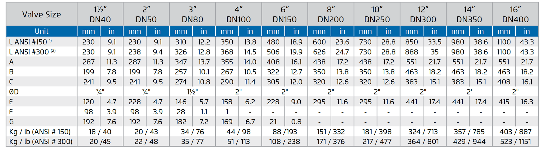
(1) Refers to the length dimensions for Raised Face ANSI #150, ISO 16 Flanged, Threaded and Grooved valves
(2) Refers to the length dimensions for Raised Face ANSI #300 and ISO 25 Flanged valves
IMPORTANT: Dimensions for the trim envelope or extents refer to a vertical orientation and may vary with specific component positioning; - allow a tolerance of at least ±10%.
Due to the wide range of options and criteria for correct model selection, pricing and configuration are available on application only.
Please contact us for more information.