| Brand: | Talgil |
| Category: | Irrigation-Automation, RTUs - Remote Terminal Units , Analog, Digital & SDI Sensors |
Product Descriptions
The LIN Expansion series extends the capabilities of the Talgil Modular RTU and DREAM2 controller, offering flexible I/O options to meet a wide range of field application needs.
Compatible with RTU RF G5 (in G5 FAST mode) and DREAM2 Controllers, LIN cards connect via the dedicated LIN Port and support both parallel connection and automatic detection by the Master unit.
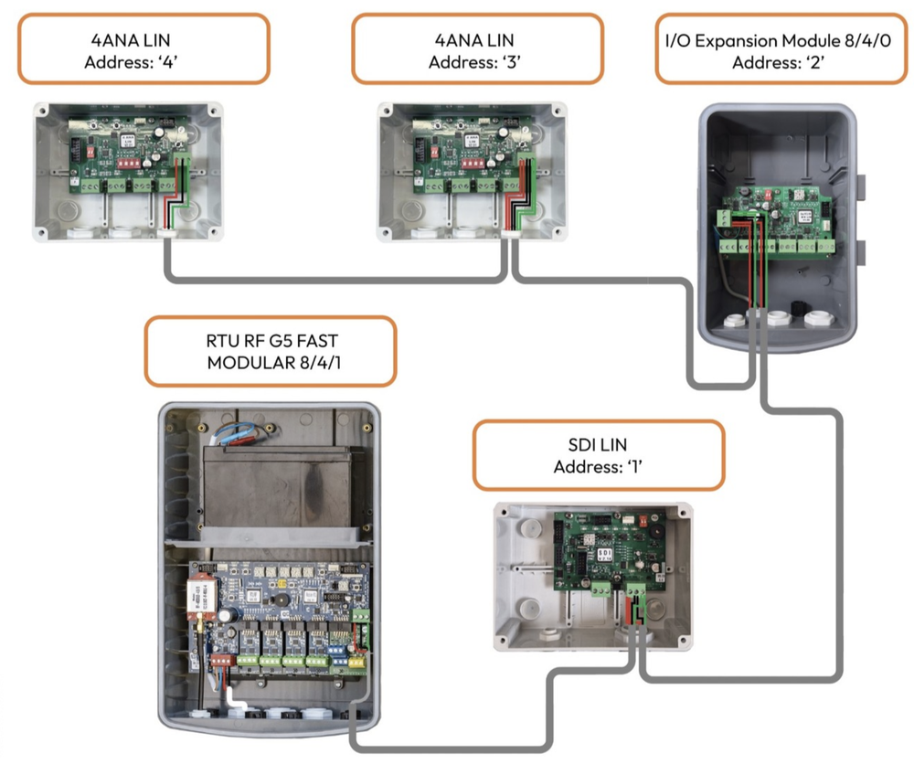
Each LIN card must be assigned a unique address when multiple cards of the same type are used. The Modular RTU auto-detects the card type and address, seamlessly integrating the data into the system.
Power Requirements:
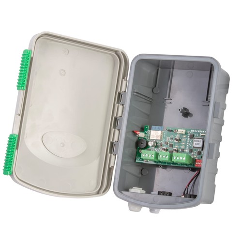
When using a LIN Expansion with the Modular RTU, a 12V DC power supply is required. Connect the rechargeable battery to the BATTERY input on the power supply plug. Charging is supported via an 18V DC source (solar panel or power supply) connected to the CHARGE input.
Available LIN Expansion Models
At this stage - the following LIN Expansion Models are available:
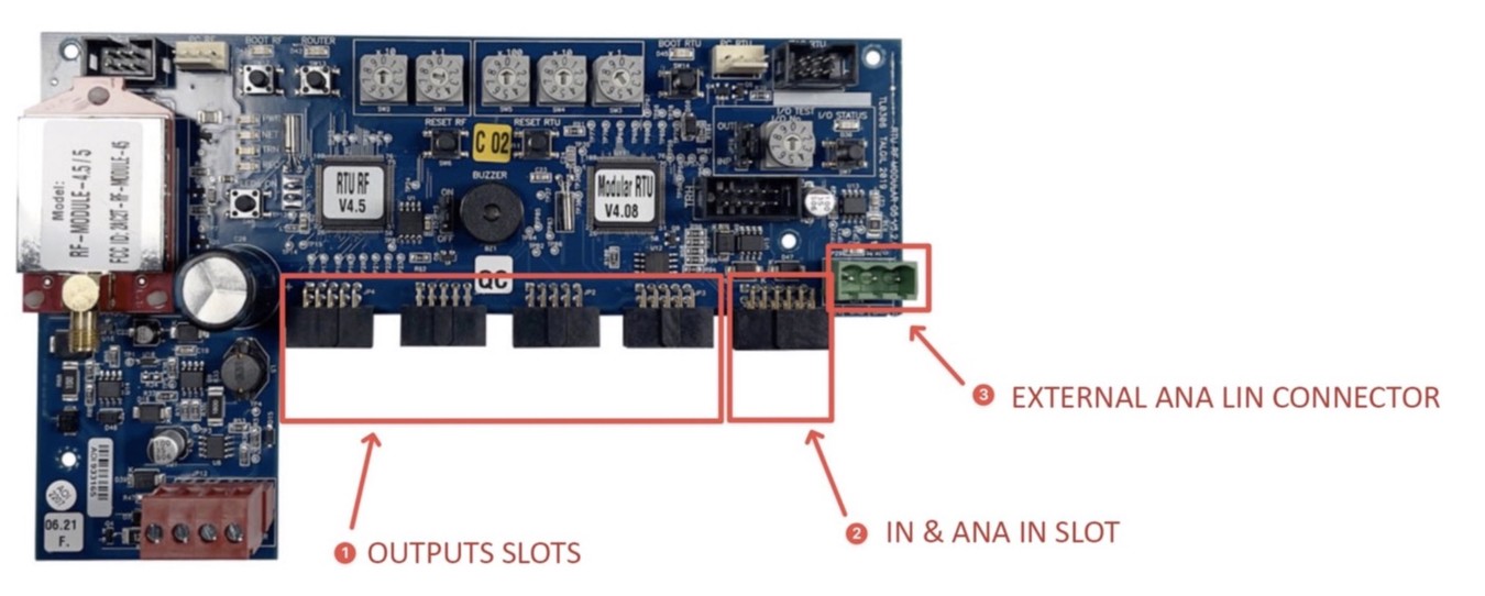
- 4 ANA LIN (4 ANALOG INPUTS)
- 840 LIN (8 OUTPUTS / 4 DIGITAL INPUTS / 0 ANALOG INPUTS)
- MODBUS LIN
- SDI LIN
In G5 Fast, there is an option to connect several LIN cards in parallel. When connecting several LIN cards of the same type to the RTU Modular, set up a unique address for every LIN card. The RTU Modular automatically detects the LIN card type, and LIN card address, and transmits the LIN card type, address, and the LIN card Data to the Master unit.
MODBUS LIN Expansion Module:
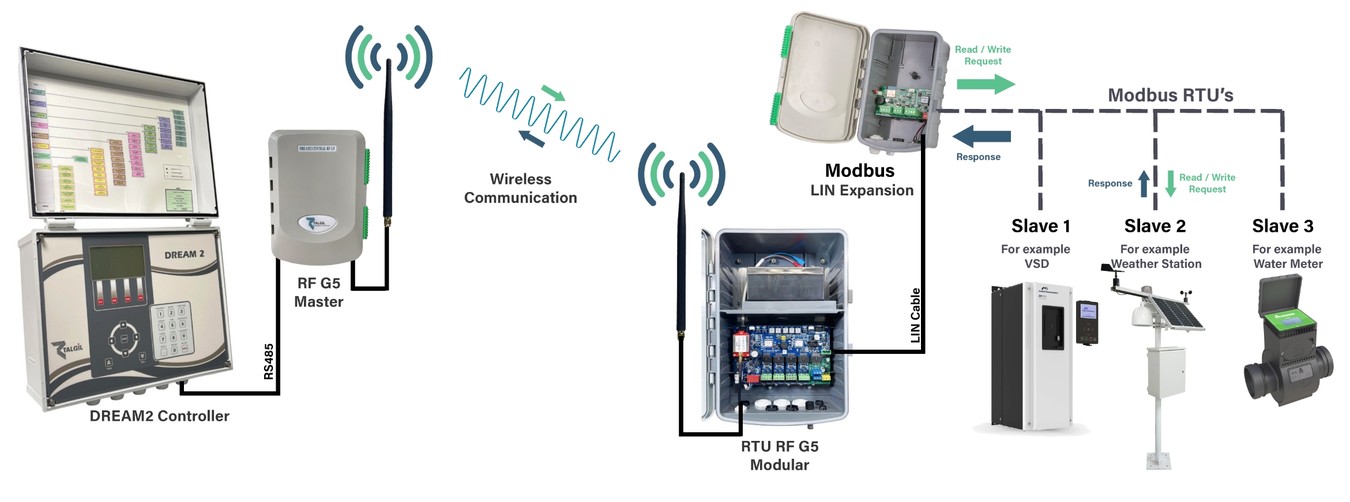
The MODBUS LIN Expansion allows integration between the Talgil system and third-party Modbus RTU devices, such as pumps, VSDs, valves, and sensors. This unit connects via the LIN port to any G5 Modular RTU (FAST MODE) or directly to the DREAM2 Controller (via RS485 Bridge).
- Supported Modbus Functions
The LIN Expansion enables both control and monitoring through four Modbus function types:
- Write Coils (Displayed as Satellites in DR2)
- Example: Start/stop pumps, open/close valves, activate filters or injectors
- Write Only - Address Range: 00001....09999
- Read Discrete Inputs (Displayed as Contacts in DR2)
- Example: Monitor pump status, float switches, digital pressure sensors
- Read Only - Address Range: 10001....19999
- Read Holding/Input Registers (Displayed as Analog Inputs / Contacts in DR2)
- Example: Read flow rate, pressure, temperature
- Read Only - Address Range: 30001....39999
- Write Holding Registers (Displayed as Analog Outputs in DR2)
- Example: Send setpoints (e.g., target pressure) to Modbus devices
- Read / Write - Address Range: 40001....49999
- Capacity:
- 64 Digital Outputs (Coils)
- 64 Digital Inputs (Discrete Inputs)
- 64 Analog Inputs (Registers)
- 64 Analog Outputs (Writable Registers)
- Programming Tool:
- Modeler Software: This software creates a Modbus RTU model. The model includes a list of register types, register addresses, units, hysteresis, and description.
- MBI Configurator: Loads the saved configuration into the DREAM2 Controller (via config file)
- Control and monitoring up to four modbus RTUs
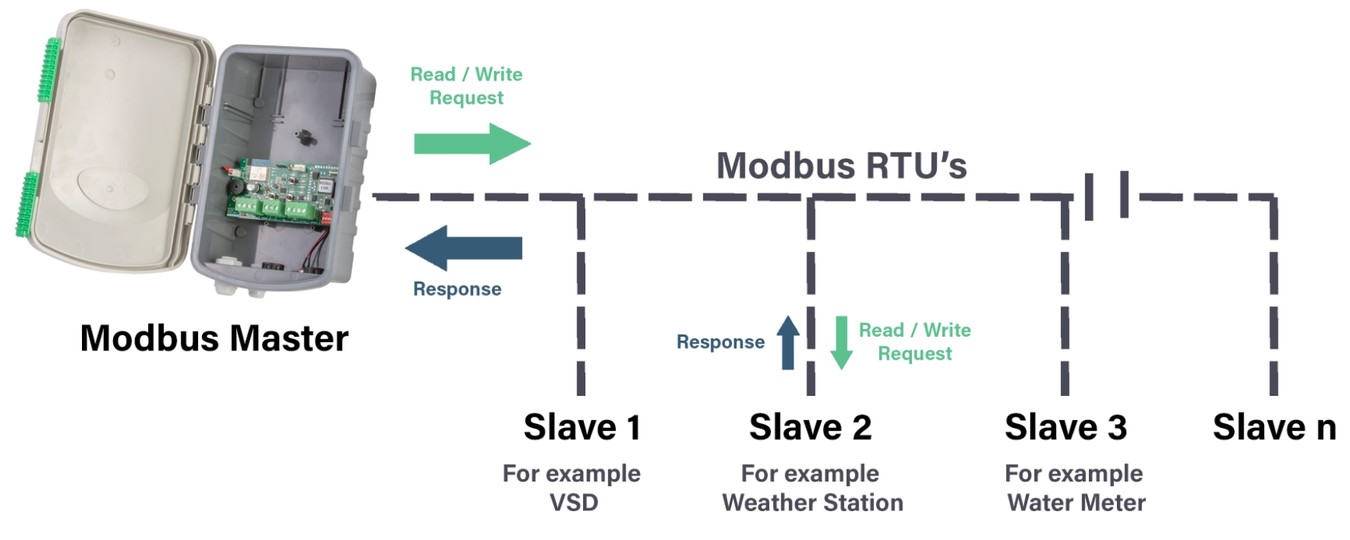
How Does Modbus RTU Work?
Modbus RTU communicates via serial lines in a request-response manner. The master device initiates a communication request, and the slave device responds with the requested data or confirmation.
MODBUS interface (MBI)
The Modbus Interface (MBI) is a dedicated hardware module that acts as a gateway between the master controller and external Modbus-compatible devices. It enables the system to communicate with field devices using the Modbus RTU protocol over RS485.
RS485 is a physical (electrical) standard that defines how devices communicate electrically. It’s not a protocol itself, but a wiring standard that supports long-distance, high-speed, and noise-resistant communication.
Cable Length: The maximum cable length for RS485 is approximately 1,200 meters.
The protocol is used in systems such as Supervisory Control and Data Acquisition (SCADA), remote monitoring, and process control.
The basic process of Modbus RTU communication involves:
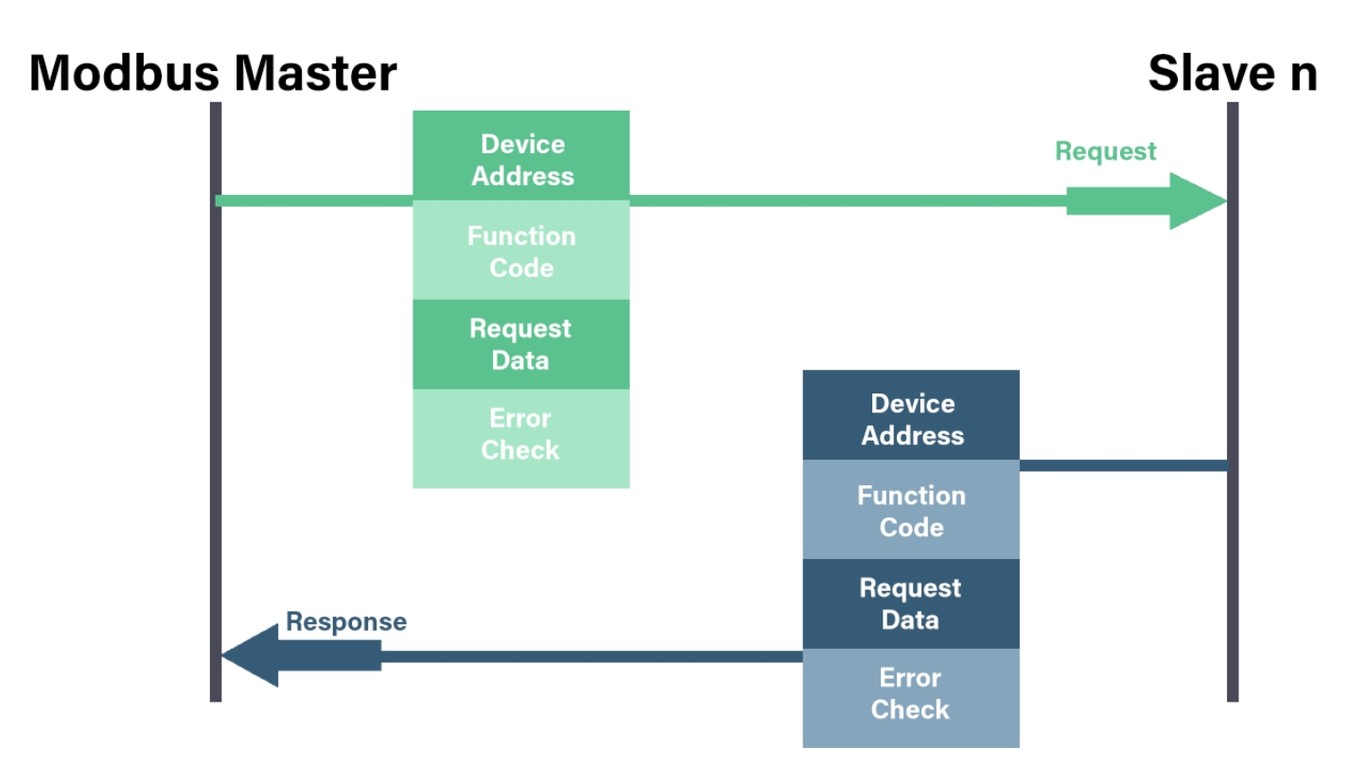
- 1. Request: The master sends a message requesting specific data or actions from the slave. The message typically includes the slave’s address, the function code (specifying the action), and any required data.
- 2. Response: The slave device receives the request, processes it, and sends back a response. The response may include data or an acknowledgment of a successful action.
- 3. Error Checking: Modbus RTU includes error-checking mechanisms, such as Cyclic Redundancy Check (CRC), to ensure data integrity. If the data transmission is incorrect, the master can request a retransmission.
Each message in Modbus RTU is transmitted in a binary format, allowing for efficient and compact data exchange. Communication speeds typically range from 9600 to 115200 baud, and each message is structured to be easily interpreted by the master and slave devices.
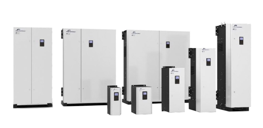
Example of Modbus RTU - Power Electronics - SD750 SERIES VSD
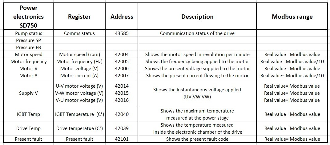
Example: Selected Values for Communication with Talgil System
System Installation Showcase
VSD: Power Electronics SD750
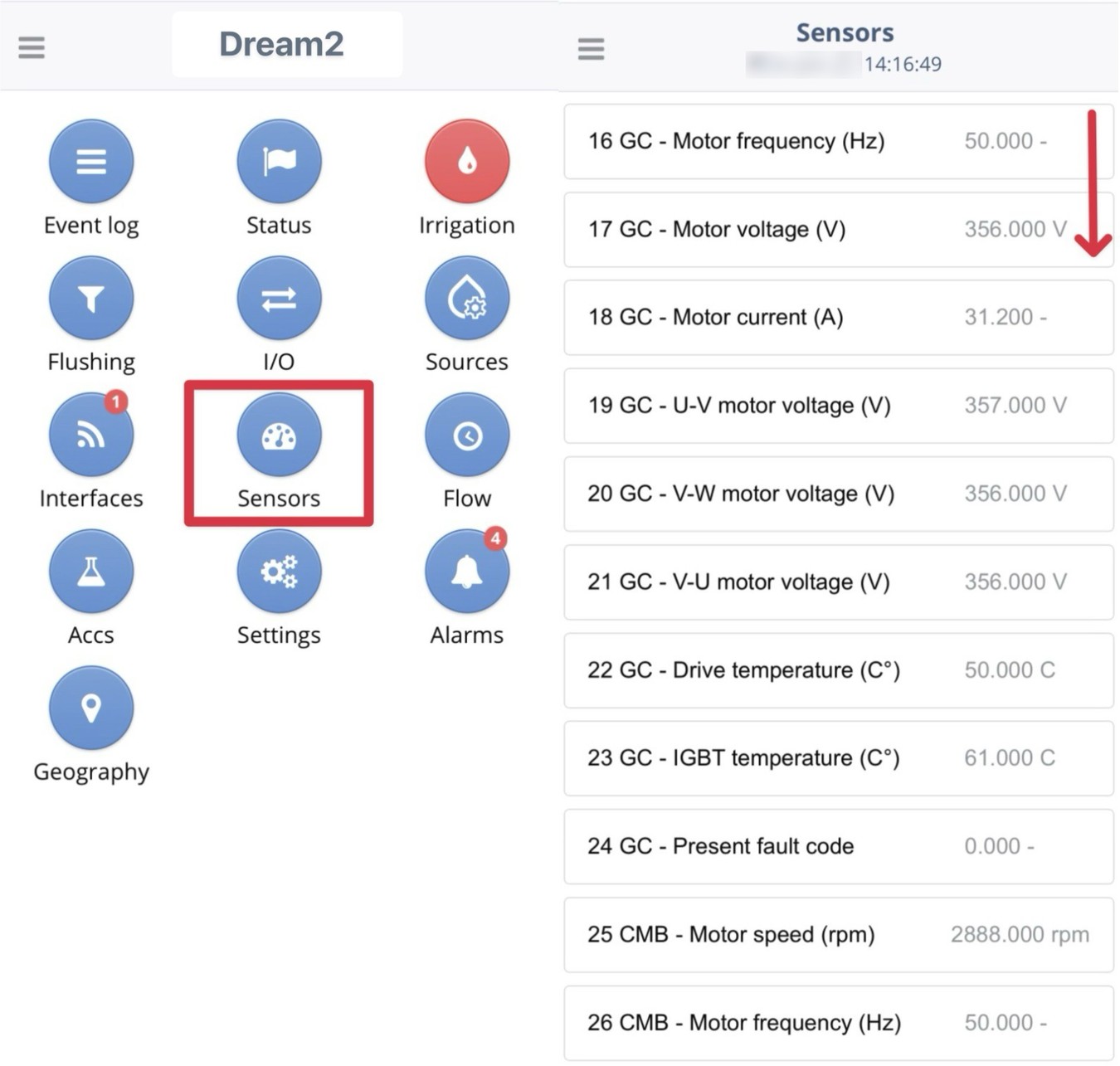
Each VSD shows the following:
- Motor Speed - rpm - The actual rotational speed of the motor shaft in revolutions per minute.
- Motor Frequency - Hz - The electrical frequency the drive is outputting to the motor, which directly controls the motor's speed.
- Motor Voltage - V - The effective AC voltage being applied to the motor terminals.
- Motor Current - A - The total electrical current (Amps) the motor is drawing from the drive; used to monitor load.
- U-V Motor Voltage - V - The voltage measured between output phases U and V.
- V-W Motor Voltage - V - The voltage measured between output phases V and W.
- V-U Motor Voltage - V - The voltage measured between output phases W and U. (Comparing these three confirms phase balance).
- Drive Temperature- The internal ambient temperature inside the VSD cabinet or control board area.
- IGBT Temperature- The temperature of the Insulated-Gate Bipolar Transistors (the power switches). This is the most critical thermal value to prevent overheating.
- Alarm Code - A numeric ID representing the specific error or fault currently active
List of the most common Alarm IDs (Fault Codes) for the SD750 series.
0-No Fault - System is healthy.
1 - Overcurrent - Short circuit, motor winding failure, or aggressive acceleration.
2 - Overvoltage - Deceleration too fast (regen energy), or high input grid voltage.
3- Undervoltage - Input power sag or phase loss.
4 - Input Phase Loss - One of the 3-phase input lines is disconnected or blown fuse.
5- Output Phase Loss - Wire to motor is loose or motor winding open.
6 - Motor Overload - Motor is drawing high current for too long (Thermal model trip).
7 - Drive Overload - VSD IGBTs are working beyond rated capacity.
8 - IGBT Temperature - Critical Overheat. Check fans and cabinet airflow.
9 - Drive Temperature - Internal ambient temp too high.
10 - Ground Fault - Current leaking to earth (insulation failure).
11 - Thermistor (PT100) - Motor temp sensor (if connected) indicates overheat.
Talgil Console Software Software - Values Preview
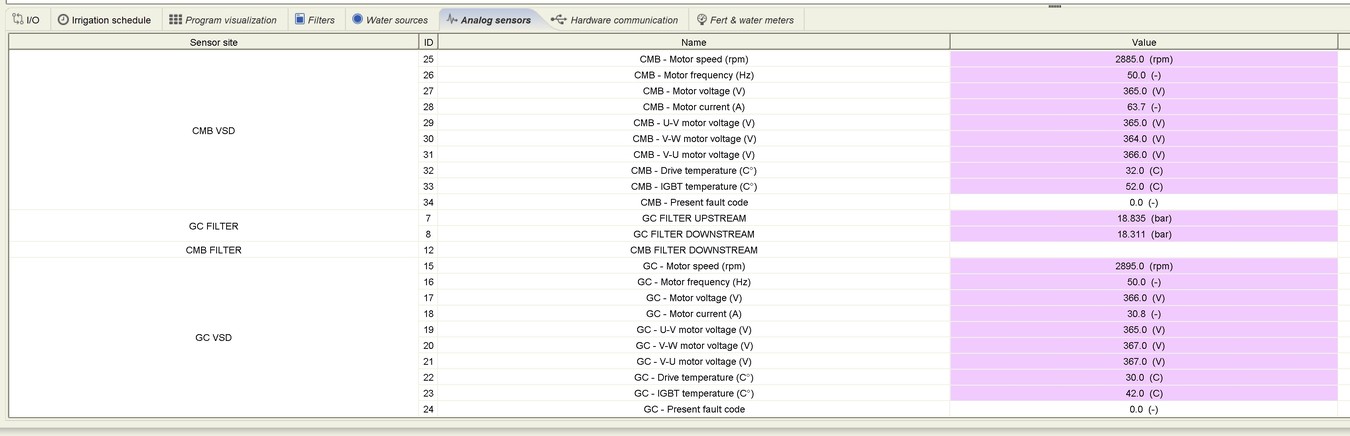
Console Software - Realtime values
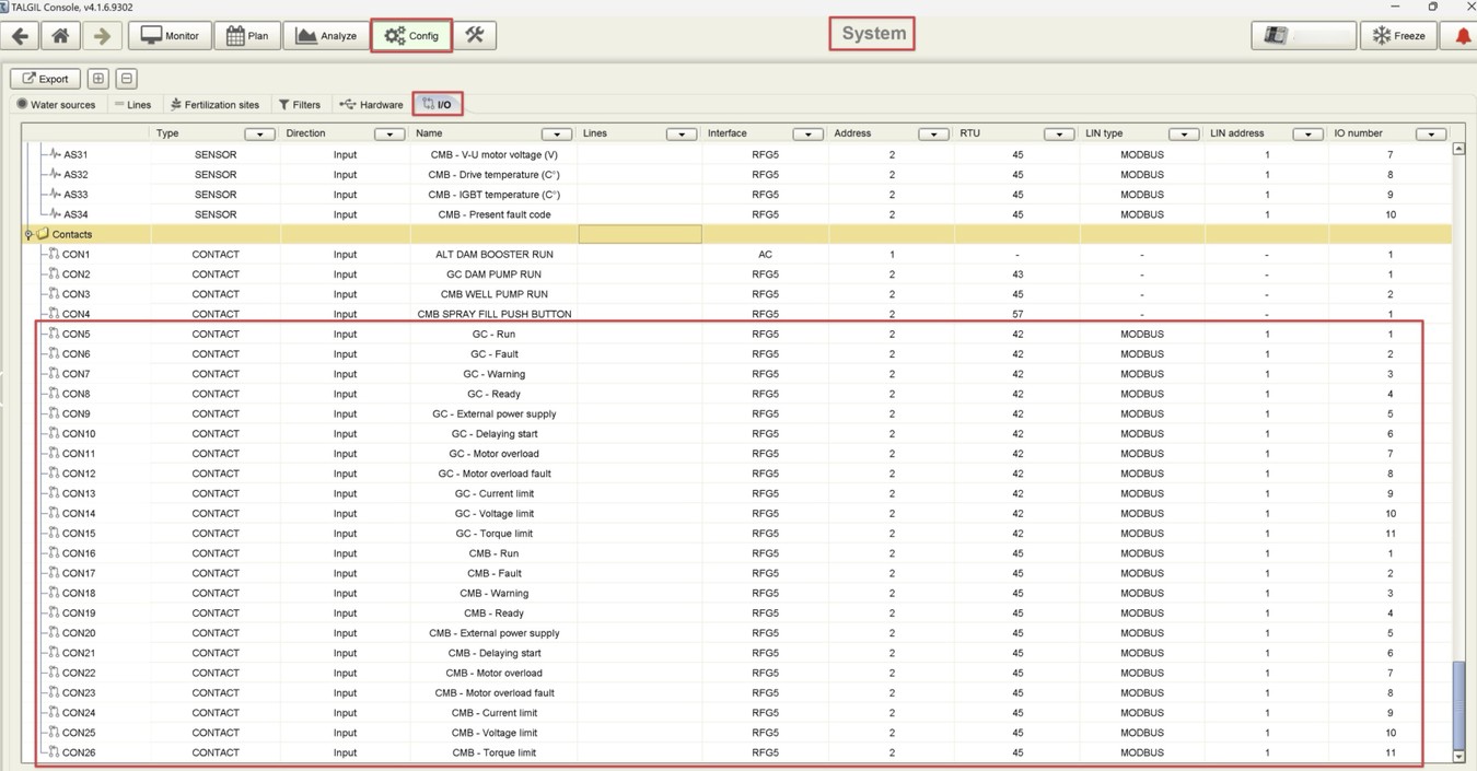
Console Software - I/O Preview
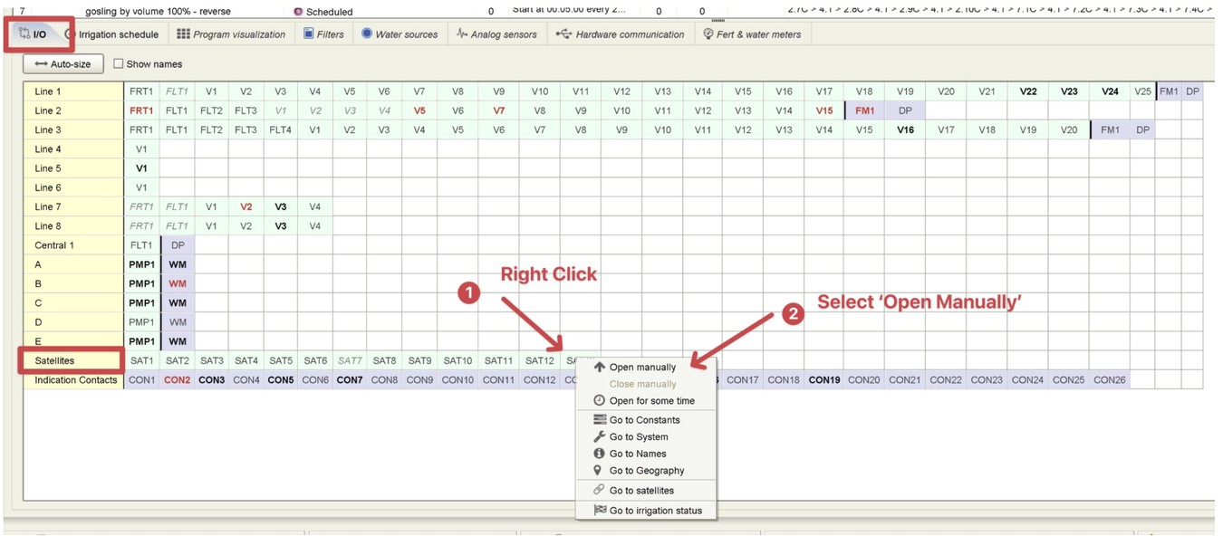
Console Software - Remote VSD Reset
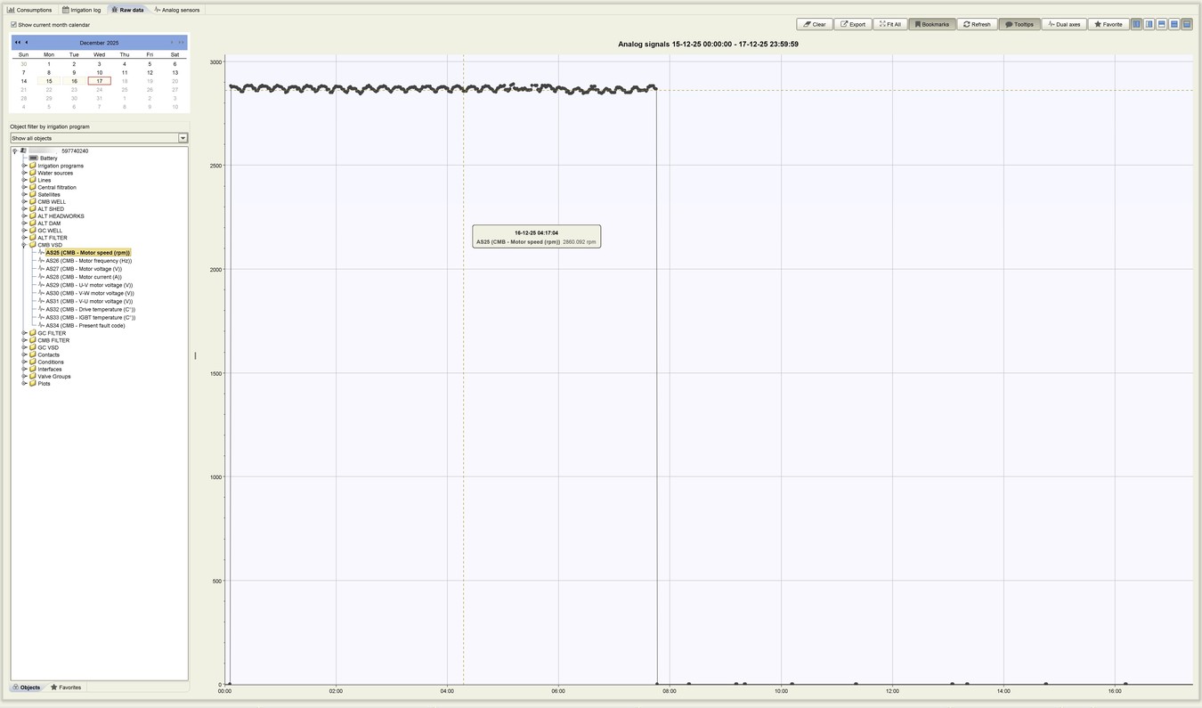
Console Software - Anlyze Section - VSD Speed (rpm) history
Talgil - Spot3 Mobile App - Values Preview
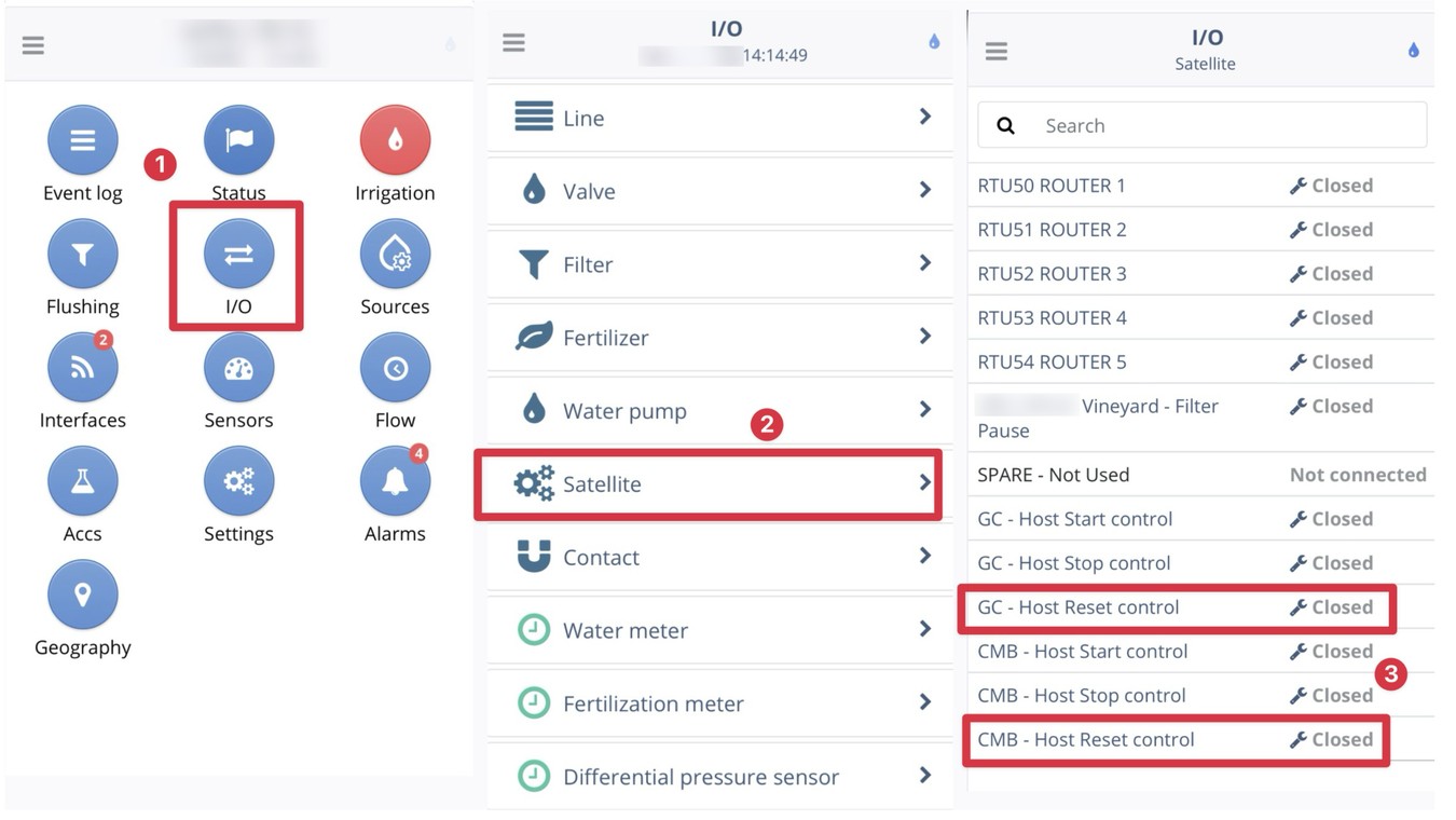
Spot3 Mobile App - Remote VSD Reset
FOR MORE CONFIGURATION OPTIONS - Visit the Ordering Guide - RTU RF G5


