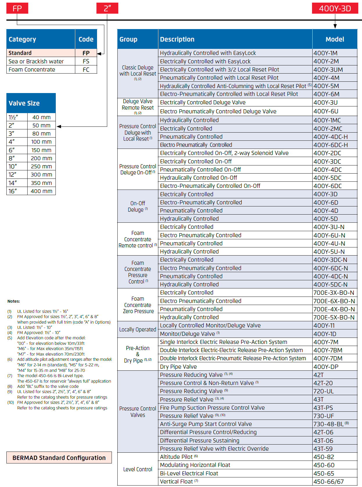
| Brand: | Bermad |
| Category: | Control Valves, Fire Protection Series |
| Size Range: | 50-400mm |
| Connection: | 50 - 400mm - Flanged 80 - 200mm - Grooved |
Product Description
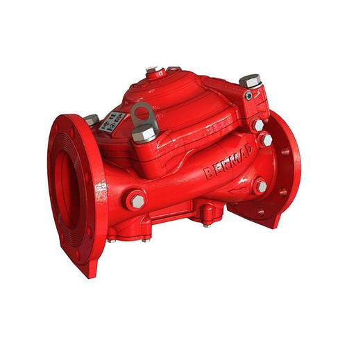
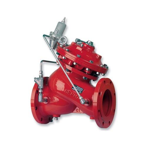
BERMAD 700E Deluge Valves are Y-type globe valves with integral unitized double chamber actuator that consists of one single moving assembly, which includes a diaphragm assembly, a flat seal disk, and a stainless steel removable seat. These automatic water control valves are designed for high-pressure service, in vertical or horizontal installations, and are available in diameter sizes from 1½” to 16”; DN40 to DN400.
The BERMAD 700E valves are used for water flow control in Deluge, Pressure Control Deluge, Preaction, or Water/ Foam systems, and are manufactured from materials suitable for freshwater or alternative for seawater, foam concentrate, or other corrosive fluids.
The 700E Deluge Valve is held closed by system water pressure trapped in the control chamber. When the releasing system operates, pressure is released from the control chamber, and the seal disc opens to allow water to flow into the system.
The 700E valve body design includes a single, full-bore seat with an unobstructed flow path, free of any in-line ribs, supporting cage, or stem guides. The 700E “Y Type” design provides high-flow capabilities with minimum head loss.
The integral unitized double-chambered actuator provides a combination of positive, immediate response with smooth hammer-free, drip-tight closing.
The whole actuator can be easily removed for a quick in-line inspection and servicing.
Valve actuation is accomplished by one moving assembly which includes a replaceable flat diaphragm, harnessed to the diaphragm assembly, a stainless steel stem, and a flat seal disk assembly.
The balanced seal-disk assembly with its resilient seal enables controlled actuation, high durability, and perfect drip-tight sealing, even under harsh conditions.
Features & Benefits
- High-Pressure Construction – 28 bar rating available
- Integral unitized double chamber actuator with single-moving assembly
- In-line serviceable, field replaceable internals
- Obstacle-free, full-bore
- Available in corrosion-resistant materials
- Designed to be reset without opening the valve
- Compatible with electric/hydraulic/pneumatic release and pressure control trim systems
Approvals
- UL Listed to UL 260 from 5 to 300 psi; 0.3 to 21 bar WP, 2” through 10”; DN50 through DN250
- ABS Approved for 300 psi; 21 bar WP, 1½” through 12”; DN40 through DN300
- Lloyd’s Register Type Approval for 300 psi; 21 bar WP, 1½” through 16”; DN40 through DN400
- Fire Test Certified to ISO 6182 part 5, 1½” through 16”; DN40 through DN400
Notes:
- The 700E valve shall be trimmed with specific components & accessories
- The 700E valve must be installed and maintained in compliance with the most recent BERMAD publications.
Accessories
The BERMAD 700E Deluge Valve shall be trimmed with the original components and accessories per specification and in accordance with valve functions and applications. Where additional specifications and/or signaling devices are required for a specific application, refer to system data for the system used, and to the BERMAD data sheet and Installation, Operation & Maintenance for the specific model required.
Technical Data
Construction Materials
The BERMAD 700E valves are available in a variety of materials to ensure optimal suitability for a wide range of applications. For operations involving exposure to internal and/or external corrosive conditions, valves are constructed from corrosion-resistant materials making them suitable for use with seawater, brackish water, or corrosive environments such as seashores, petrochemicals, and other industrial facilities.

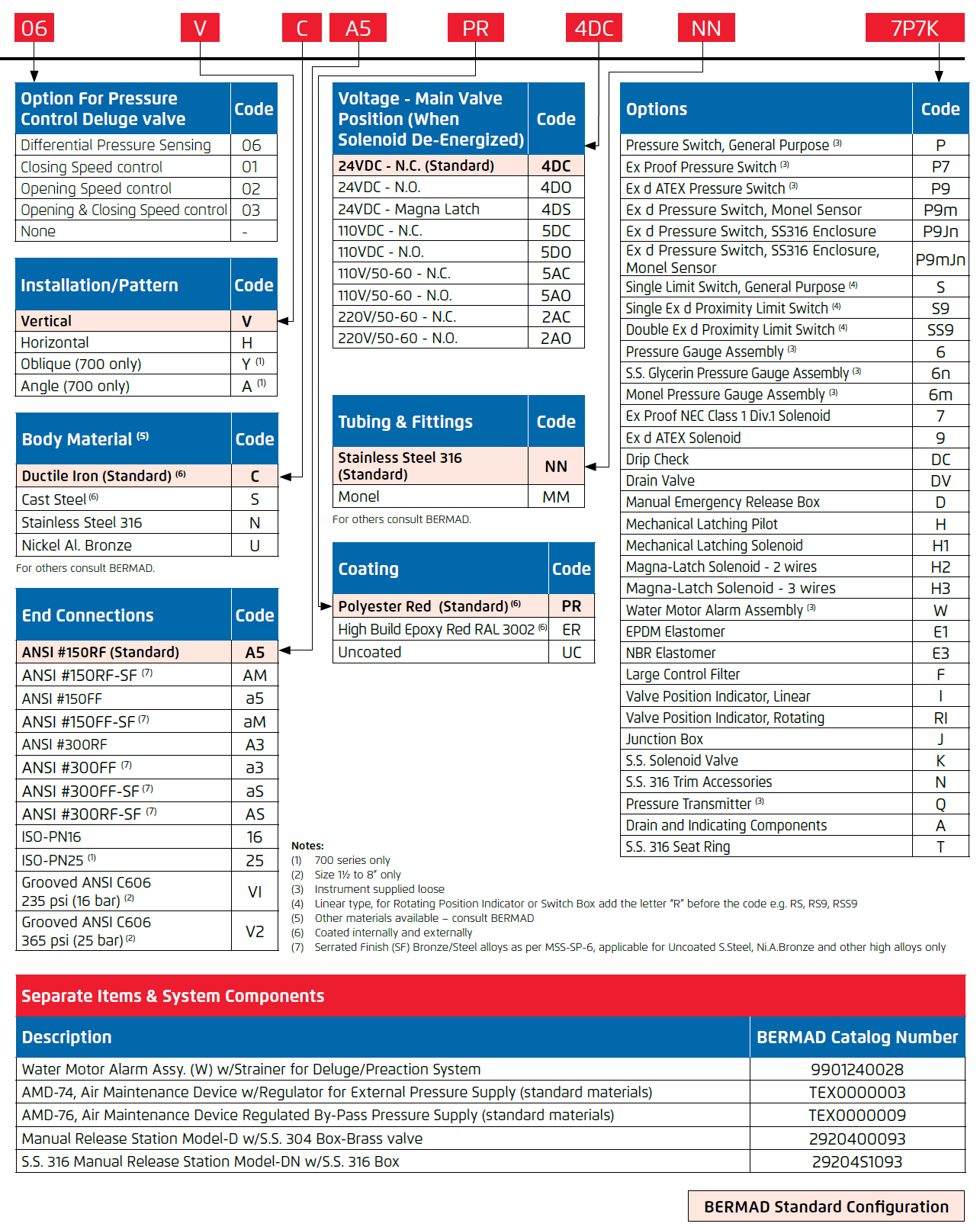
Standard Configurations

Specifications
Castings:
- Ductile Iron to ASTM A536 65-45-12 (coated)
- Cast Steel ASTM A216 Grade WCB (coated)
- Nickel Aluminum Bronze ASTM B148 C95800
- Stainless Steel 316 ASTM A351 Grade CF8M
- Super Duplex ASTM A890 Grade 5A
- Hastelloy C-276
Bolting:
- External Bolting: S.S.316 to ASTM A320 Gr.B8F
Internal Wetted Parts:
- Stainless Steel 303 ASTM A582 95B S30300A
- Stainless Steel 304 ASTM A743 Grade CF8
- Stainless Steel 431 ASTM A743 Grade CA15M
- Bronze ASTM B505 Grade C83600
- Internal Spring - S.S. 302
Optional Internal Wetted Parts:
- Stainless Steel 316 ASTM A351 Grade CF8M
- Nickel Aluminum Bronze ASTM B148 C95800
- Monel 400
- Super Duplex ASTM A890 Grade 5A
- Hastelloy C-276
- Internal Spring - Inconel
Elastomers
- NBR, Polyamide fabric reinforced Nitrile (Buna-N), Temperature Rating 80°C
- EPDM, Polyamide fabric reinforced Ethylene-Propylene, Temperature Rating 90°C
Coating
- Electrostatic Powder Coating Polyester
- High Built Epoxy Fusion-Bonded with UV Protection, Anti-Corrosion
- Color: Fire Red to RAL 3002
Note: Internal & external coating applied on Ductile Iron or Cast Steel Castings only.

Notes
1. Factory pressure testing: Each valve is tested at 1.6 of pressure rating.
2. Water Temperature: 0.5 - 80ºC (33 - 122ºF)
3. Standard flange facing: Raised Face (RF), Serrated Finish. Flat-face (FF) flanges are available on request.
Principle of Operation
The BERMAD 700E Deluge Valve (assembled with specific trim) is suitable for systems that include adequate detecting and piping systems with open nozzles. The deluge valve prevents water from entering the system piping until required. The deluge valve is kept closed by pressure applied to the upper control chamber through a restricted priming line.
In the SET position, the water pressure supplied through the priming line is trapped in the upper control chamber of the deluge valve by a check valve, and by the normally closed release device.
The pressure trapped in the upper control chamber of the deluge valve presses the valve seal disk down, thereby sealing the valve and keeping the system piping dry.
Under conditions of FIRE, when the pressure is released from the upper control chamber by the opening of the automatic releasing device or by manual release, the deluge valve opens and allows the inlet supply water to flow through the valve and into the system piping and alarm devices.
Warning: Whenever the handle of the Manual Emergency Release is pulled, pressure is released from the upper control chamber, the deluge valve will open, and water will flow into system piping and alarm devices.

Line pressure was applied to the upper control chamber of the valve creates a superior force that moves the valve to the closed position and provides drip-tight sealing

Releasing the pressure from the upper control chamber to the atmosphere or some other lower pressure zone causes the line pressure acting on the seal disc to move the valve to the open position.
Flow Chart

Flow Properties

Valve flow coefficient, Kv or Cv
Kv(Cv)=Q√Gf/ΔP
Where:
Kv = Valve flow coefficient (flow in m3/h at 1bar Diff. Press.)
Cv = Valve flow coefficient (flow in gpm at 1psi Diff. Press.)
Q = Flow rate (m3/h ; gpm)
ΔP = Differential pressure (bar ; psi)
Gf = Liquid specific gravity (Water = 1.0)
Cv=1.155Kv
Flow resistance or Head loss coefficient, K=ΔH(2g/V²)
where:
K = Flow resistance or Head loss coefficient (dimensionless)
ΔH = Head loss (m ; feet)
V = Nominal size flow velocity (m/sec; feet/sec.)
g = Acceleration of gravity (9.81 m/sec2 ; 32.18 feet/sec2)
Equivalent Pipe Length, Leq
Leq=L.D
where:
Leq = Equivalent nominal pipe length (m; feet)
Lk = Equivalent length coefficient for turbulent
flow in clean commercial steel pipe (SCH 40)
D = Nominal pipe diameter (m; feet)
Note:
The Leq values given are for general consideration only.
Actual Leq may vary somewhat with each of the valve sizes
Technical Specifications
Dimensions and Weights


(1) (a), (b), (c) are NPT thread ports
(2) (d) is BSPT threaded Optional drain port
(3) (Control Volume) is Control Chamber Displacement Volume of liquid pushed when valve opens
(4) LG for Grooved ends (see available sizes)
Placing in Service/Resetting
The deluge valve and the control trim shall be Placed in Service in accordance with the most recent IOM procedures for the specific model. After all relevant instructions are performed, slowly open the supply-isolating valve and check that no water flows into the system. The system is now operational and in standby mode.
Maintenance
Bermad Deluge Valves require no lubrication, no packing tightening, and require a minimum of maintenance
Removing the System from Service
Warning:
When taking a deluge system out of service, a fire patrol should be established in the system area. If automatic fire alarm signaling equipment is utilized, the proper authority should be notified that the system is being removed from service. The insuring body and owner’s representative should also be notified when the system is being taken out of service.
Removal Instructions
- Shut off the main supply-isolating valve.
- Close the priming line valve to the deluge valve control chamber.
- Open all drain valves.
- Release the water pressure from the control chamber of the deluge valve by pulling the manual emergency release.
- Place "Fire Protection System Out of Service" signs in the area protected by the system
Inspection and Testing
- Warning: Do not turn off the water supply to make repairs without placing a roving fire patrol in the area covered by the system. The patrol should continue until the system is back in service.
- Prior to turning off any valves or activating any alarms, notify local security guards and the central alarm station, if used, to avoid signaling a false alarm.
- The deluge valve and the control trim shall be maintained in accordance with the most recent IOM procedures for the specific model. A periodic test schedule should be established also in accordance with the site conditions and owner regulations.
- Take all additional measures as required by NFPA-25 “standard for the inspection, testing, and maintenance of water-based fire protection systems”.
- The system should be checked weekly for “Normal Conditions”
- Clean the priming strainer prior to any resetting of the deluge valve.
- The deluge valve must be activated at full flow at least annually. Take all necessary precautions to drain water and prevent damage in the area protected by the system.
- After about five years of operation, replacement of diaphragm and other elastomers is recommended. Remove the actuator and disassemble it. Clean the seat area from sediments, clean the control tubing entry holes, and install a new diaphragm and other elastomers in place.
Spare Parts
- The Diaphragm and the Seals are the only spare parts needed for the main deluge valve, see the attached “Valve Disassembly and Parts Breakdown” illustration.
- It is not recommended to store spare rubber parts for long periods (rubber in improper storage conditions can harden and crack).
- Contact your Bermad representative and order new rubber parts when required.

Due to the wide range of options available and criteria for correct model selection, pricing and configuration is available on application only.
Please contact us below for more information.