| Brand: | Bermad |
| Category: | Control Valves, 700 Series |
| Size Range: | 50-600mm |
| Connection: | EN: 50-400mm - Flanged ES: 65-600mm - Flanged |
Product Description
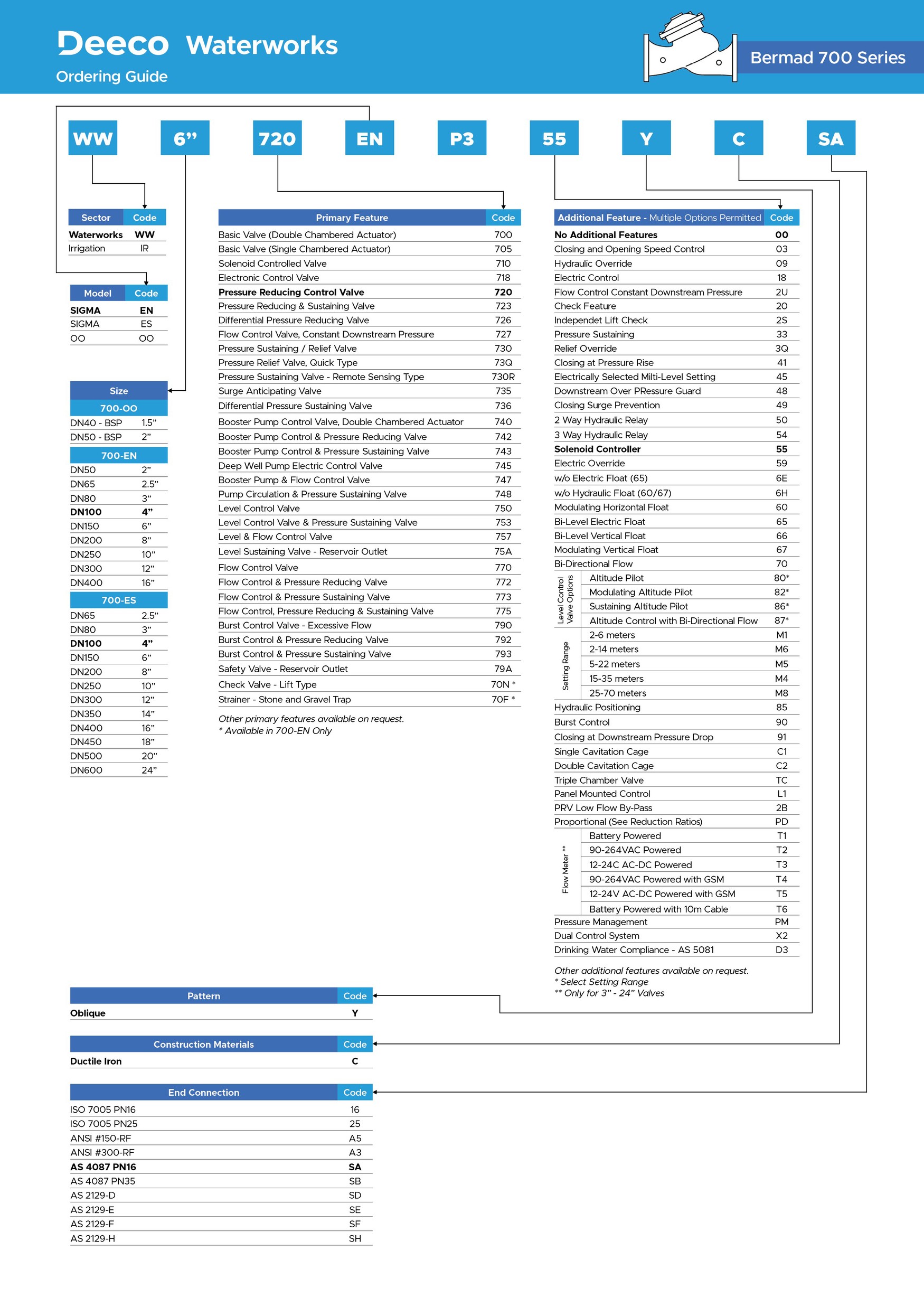
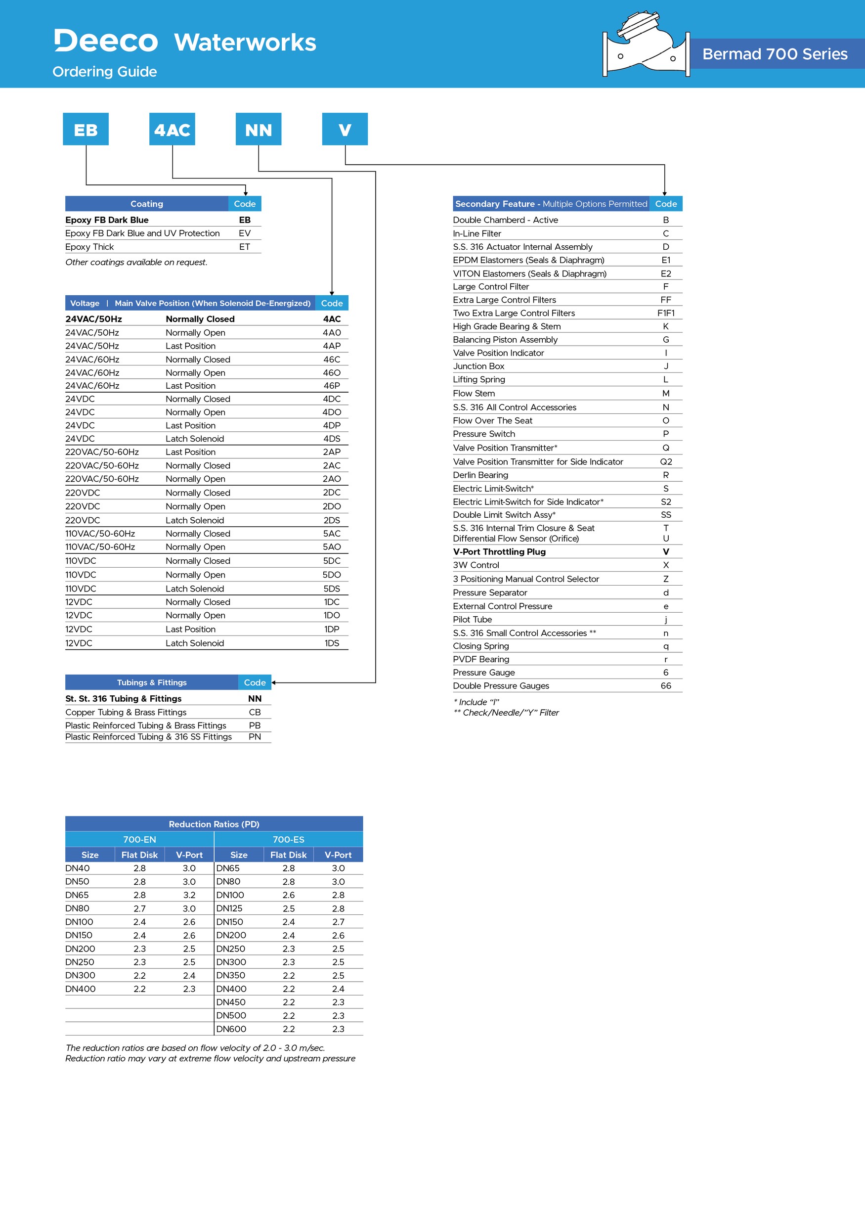
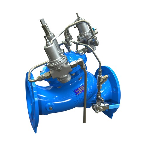
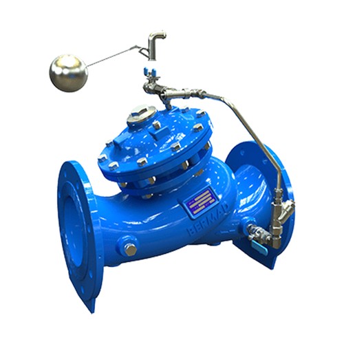
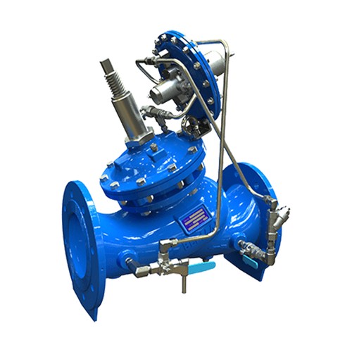
BERMAD 700 SIGMA EN/ES series are hydraulically operated, oblique pattern control valves with high cavitation resistance, excellent flow capacity and a double chamber unitized actuator, that can be disassembled from the body as a separate integral unit. The valve's hydrodynamic body is designed for an unobstructed flow path and provides excellent and highly effective modulation capacity for high differential pressure applications, with minimal noise and vibrations.

The 700 SIGMA EN/ES series meets all flange connection standards. 700 SIGMA EN – Full port valve with extraordinarily high flow capacity, enabling optimized use of resources and minimizing energy costs. 700 SIGMA ES - Designed mainly for regulating applications achieving the best performance under variable flow velocities in pipes.
Features and Options
- Double-Chambered Actuator
- The actuator assembly can be removed as one integral unit.
- Simple on-site conversion from Single to Double chambered actuator or vice versa.
- Wide Body-Oblique “Y” pattern design
- Hydro-dynamically designed for efficient flow with minimal pressure loss and excellent resistance to cavitation.
- The valve port area is clear of obstructions; no ribs or stem guides. Increases capacity by 25% over standard globe valves.
- Diaphragm Assembly
- The flexible, flat fabric reinforced diaphragm is supported over the majority of its surface
- Diaphragm load is limited to only the stretching forces applied to the active area.
- Diaphragm is fully protected by the separation partition from stones, wood and debris.
- Valves are suitable to work with all types of command: Hydraulic, Electric and Pneumatic.
- Self operated valves that can work without an external source of power.
- Wide range of options:
- One-way or two-way flow direction
- V-Port
- Cavitation cages (Single or Double)
- Visual position indicator
- Limit switches
- Analog opening output
- Large selection of control accessories.
Exploded View

Material Specifications


Principle Of Operation
On-Off Modes

3-Way Modulating Mode - Pressure Reducing

2-Way Modulating Mode - Pressure Reducing

700 SIGMA EN / ES - Technical Data

Valve Patterns: “Y” (Globe)
Pressure Rating: 16 bar - with higher pressure options available.
End Connections:
EN: 50-400mm - Flanged
ES: 65-600mm - Flanged
Plug Types: Flat disc, V-port, Cavitation cages
Temperature Rating: 60°C, for Cold water applications.
Optional higher temperature: Available on request
Standard Materials
Body & actuator: Ductile Iron
Bolts, nuts & studs: Stainless Steel
Internals: Stainless Steel, Bronze & Coated Steel
Diaphragm: Fabric-reinforced synthetic rubber
Seals: Synthetic rubber
Coating: Dark blue Fusion bonded epoxy. For other materials, contact Deeco.
Dimensions and Weights - 700 Sigma EN


* Maximum Dimensions
Flow Factors - 700 Sigma EN

Flow Chart - 700 Sigma EN

* Charts represent fully open valves.
Discuss with Deeco for proper valve sizing.

Technical Data - 700 Sigma ES
Valve Patterns: “Y” (Globe)
Pressure Rating: 16 bar - with higher pressure options available.
End Connections: 65-300mm - Flanged
Plug Types: Flat disc, V-port, Cavitation cages
Temperature Rating: 60°C, for Cold water applications.
Optional higher temperature: Available on request
Standard Materials:
Body & actuator: Ductile Iron
Bolts, nuts & studs: Stainless Steel
Internals: Stainless Steel, Tin Bronze & Coated Steel
Diaphragm: Fabric-reinforced synthetic rubber
Seals: Synthetic rubber
Coating: Dark blue Fusion bonded epoxy. For other materials, contact Deeco.
Dimensions and Weights - 700 Sigma ES


* Maximum Dimensions ** For 24’’, the dimensions is without the sizes of cradle
Flow Factors - 700 Sigma ES

Flow Chart - 700 Sigma ES

Cavitation
The cavitation phenomenon has a significant effect on the control valve and system performance.
When the fluid’s static pressure reaches liquid vapour pressure, vapour cavities (bubbles) form and grows until they violently implode by the recovered pressure downstream to the valve seat.
The implosion of these cavities generates high-pressure surges, micro jets and intensive heat, which erode valve components and downstream piping. In its final stage, cavitation flashes and chokes the flow.
The Cavitation Guide is based on the formula commonly used in the valve industry:
σ= (P2-Pv) / (P1-P2)
Where
σ= Sigma, cavitation index, dimensionless
P1 = Upstream pressure, absolute
P2 = Downstream pressure, absolute
Pv = Liquid vapor pressure, absolute (Water, 18°C = 0.02 bar-a ; 65°F = 0.3 psi-a)
Notes:
- An alternate cavitation index formula introduced by ISA is: σISA = (P1-Pv) / (P1-P2) which equals σ+1
- The charts below should be considered only as a general guide
- For optimum system and control valve application, please consult Deeco.

* Consider back pressure orifice, or consult Deeco.
Charts represent Flat plug

* Consider back pressure orifice, or consult Deeco.
Charts represent Flat plug
Single Cavitation Cage - C1

The BERMAD Single Cavitation Cage trim is designed to reduce cavitation, noise and vibration under higher differential pressure operation, as well as smart pressure reducing.
Double Cavitation Cage - C2

The BERMAD Double Cavitation Cage trim is designed to resist cavitation, cavitation damage, noise and vibration under extreme differential pressure operation, as well as smart pressure reducing.

Bermad - 700 EN ES - Valve Cage Characteristics
Additional Valve Options and Features - 700 Sigma EN/ES
BERMAD’s 700 SIGMA EN/ ES series has various plug options to enable different valve characteristics.
Flat plug - standard plug for on-off and high-flow applications.
V-Port plug - uniquely designed throttling plug. It changes the ratio of flow to stem travel, allowing a very wide flow range with relatively high-pressure reduction and providing a more accurate, stable and smoother response during pressure and flow regulation while reducing noise and vibration.
BERMAD’s 700 SIGMA EN/ ES series plugs can easily be changed before or after valve installation on-site.
Valve Plug Characteristics


Independent Lift Check - 2S
The BERMAD Independent Lift Check feature is an integral, lift-type, spring-loaded non-return trim that allows full control and regulation in the required direction and smoothly closes drip tight before flow changes direction, regardless of control status.
Back-up Safety - TC
The BERMAD backup safety feature is a Triple Chamber actuated valve, where the third control chamber enables a failsafe mechanism and is recommended in critical or sensitive water systems to ensure continuous operation of the system.
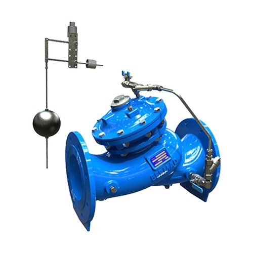
Insertion Flow Meter - MT
The BERMAD Insertion Flow Meter can be inserted into the upstream side of the 700-Sigma EN/ES valves, adding an accurate flow measurement function.

Valve Position Indicator - I
The BERMAD Valve Position Indicator Assembly provides a visual indication of valve opening and regulation behaviour.
Single Limit Switch - S
The BERMAD Single Limit Switch Assembly includes mechanical and electrical change over contacts (NO + NC), enabling remote signalling of the closed valve position.
Double Limit Switch - SS
The BERMAD Double Limit Switch Assembly includes two mechanical and electrical switches, enabling remote signalling of the closed and the open valve positions.

Flow Stem - M
The BERMAD Flow Stem Assembly enables limiting the opening stroke of the control valve or for safety-ensured mechanical closure.
Lifting Spring - L
The BERMAD Lifting Spring Assembly enables the valve to remain open at zero pressure conditions and to minimize pressure losses.
Analog Valve Position Transmitter - Q
The BERMAD Analog Valve Position Transmitter Assembly enables remote signalling of the valve’s relative position.
Repair Kits
| Product Code | Size | Description |
|---|---|---|
705040-RK |
40-65mm |
Repair Kit for 40-65mm - 700 Series Control Valve |
705040EN-RK |
40-80mm |
Repair Kit for 40-50mm EN & 65-80mm ES - 700 Series Control Valve |
705065EN-RK |
65-80mm |
Repair Kit for 65mm EN & 80mm ES - 700 Series Control Valve |
705080-RK |
80mm |
Repair Kit for 80mm - 700 Series Control Valve |
705100-RK |
100mm |
Repair Kit for 100mm - 700 Series Control Valve |
705150-RK |
150-200mm |
Repair Kit for 150mm EN & 200mm ES - 700 Series Control Valve |
705150ES-RK |
150mm |
Repair Kit for 150mm ES - 700 Series Control Valve |
705200-RK |
200-250mm |
Repair Kit for 200mm EN & 250mm ES - 700 Series Control Valve |
705250-RK |
250-300mm |
Repair Kit for 250mm EN & 300mm ES - 700 Series Control Valve |
705300-RK |
300-350mm |
Repair Kit for 300mm EN & 350mm ES - 700 Series Control Valve |
705400-RK |
400mm |
Repair Kit for 400mm EN & 400mm ES - 700 Series Control Valve |

| Pos. | Description | Qty |
|---|---|---|
1 |
1.5"-3"R(700), NBR Diaphragm |
1 |
2 |
1.5"-3R(700), NBR Seal 80 SHORE - Standard |
1 |
3 |
O-Ring NBR parker 5-617 |
2 |
4 |
O-Ring NBR parker 2-018 |
1 |
5 |
O-Ring NBR parker 2-232 |
1 |
6 |
O-Ring NBR parker 2-020 |
1 |
7 |
O-Ring NBR parker 2-119 |
1 |
8 |
O-Ring NBR parker 2-012 |
3 |

| Pos. | Description | Qty |
|---|---|---|
1 |
1.5"-3"R(700), NBR Diaphragm |
1 |
2 |
3"(700ES), NBR Lower Seal 80-5 SHORE |
1 |
3 |
O-Ring NBR parker 5-617 |
2 |
4 |
O-Ring NBR parker 2-018 |
1 |
5 |
O-Ring NBR parker 2-232 |
1 |
6 |
O-Ring NBR parker 2-020 |
1 |
7 |
O-Ring NBR parker 2-119 |
1 |
8 |
O-Ring NBR parker 2-012 |
3 |

| Pos. | Description | Qty |
|---|---|---|
1 |
2.5"(700 Sigma EN) Diaphragm (1.3mm) |
1 |
2 |
2.5"(700 Sigma EN & 3" 700ES-WD NSF61), Seal 80 SHORE |
1 |
3 |
O-Ring 2-012 EPDM |
2 |
4 |
O-Ring 2-237 EPDM 70 SHORE |
1 |
5 |
O-Ring 2-118 EPDM 70 SHORE |
1 |
6 |
O-Ring 2-120 EPDM 70 SHORE |
1 |
7 |
O-Ring 2-119 EPDM |
1 |
8 |
O-Ring 5-617 EPDM |
3 |

| Pos. | Description | Qty |
|---|---|---|
1 |
3" NBR Diaphragm |
1 |
2 |
3" NBR Seal 80 SHORE |
1 |
3 |
O-Ring NBR parker 5-617 |
2 |
4 |
O-Ring NBR parker 2-237 |
1 |
5 |
O-Ring NBR parker 2-118 |
1 |
6 |
O-Ring NBR parker 2-119 |
1 |
7 |
O-Ring NBR parker 2-120 |
1 |
8 |
O-Ring NBR parker 2-121 |
1 |
9 |
O-Ring NBR parker 2-012 |
3 |

| Pos. | Description | Qty |
|---|---|---|
1 |
4"-5"(700), NBR Diaphragm |
1 |
2 |
4"-5" (700), NBR Seal 80 SHORE |
1 |
3 |
O-Ring NBR parker 5-617 |
2 |
4 |
O-Ring NBR 114x4 |
1 |
5 |
O-Ring NBR parker 2-118 |
1 |
6 |
O-Ring NBR parker 2-119 |
1 |
7 |
O-Ring NBR parker 2-120 |
1 |
8 |
O-Ring NBR parker 2-121 |
1 |
9 |
O-Ring NBR parker 2-012 |
3 |

| Pos. | Description | Qty |
|---|---|---|
1 |
6"(700), NBR Diaphragm |
1 |
2 |
6" (700), NBR Seal 80 SHORE |
1 |
3 |
O-Ring NBR parker 5-617 |
2 |
4 |
O-Ring NBR parker 2-364 |
1 |
5 |
O-Ring NBR parker 2-124 |
1 |
6 |
O-Ring NBR parker 2-126 |
1 |
7 |
O-Ring NBR parker 2-227 |
1 |
8 |
O-Ring NBR parker 2-212 |
3 |

| Pos. | Description | Qty |
|---|---|---|
1 |
6"(700ES), NBR Diaphragm |
1 |
2 |
6" (700), NBR Seal 80+5 SHORE |
1 |
3 |
O-Ring NBR parker 5-617 |
2 |
4 |
O-Ring EPDM 2-250 |
1 |
5 |
O-Ring NBR parker 2-359 |
1 |
6 |
O-Ring NBR parker 2-011 |
2 |
7 |
O-Ring NBR parker 2-124 |
1 |
8 |
O-Ring NBR parker 2-126 |
1 |
9 |
O-Ring NBR parker 2-227 |
1 |
10 |
O-Ring NBR parker 2-212 |
3 |

| Pos. | Description | Qty |
|---|---|---|
1 |
8"(700), NBR Diaphragm |
1 |
2 |
8" (700), NBR Seal 80 SHORE |
1 |
3 |
O-Ring NBR parker 2-372 |
1 |
4 |
O-Ring EPDM 2-116 |
2 |
5 |
O-Ring NBR parker 2-127 |
1 |
6 |
O-Ring NBR parker 2-129 |
1 |
7 |
O-Ring NBR parker 2-130 |
1 |
8 |
O-Ring NBR parker 2-227 |
1 |
9 |
O-Ring NBR parker 2-216 |
3 |

| Pos. | Description | Qty |
|---|---|---|
1 |
10"(700), NBR Diaphragm |
1 |
2 |
10" (700), NBR Seal 80 SHORE |
1 |
3 |
O-Ring NBR parker 2-379 |
1 |
4 |
O-Ring NBR parker 2-118 |
2 |
5 |
O-Ring NBR parker 2-130 |
1 |
6 |
O-Ring NBR parker 2-132 |
1 |
7 |
O-Ring NBR parker 2-133 |
1 |
8 |
O-Ring NBR parker 2-227 |
1 |
9 |
O-Ring NBR parker 2-218 |
3 |

| Pos. | Description | Qty |
|---|---|---|
1 |
12-14"(700), NBR Diaphragm |
1 |
2 |
12-14" (700), NBR Seal 80 SHORE |
1 |
3 |
O-Ring NBR parker 2-456 |
1 |
4 |
O-Ring NBR parker 2-326 |
2 |
5 |
O-Ring NBR parker 2-120 |
2 |
6 |
O-Ring NBR parker 2-135 |
1 |
7 |
O-Ring NBR parker 2-139 |
1 |
8 |
O-Ring NBR parker 2-139 |
1 |
9 |
O-Ring NBR parker 2-223 |
1 |
10 |
O-Ring NBR parker 2-227 |
1 |

| Pos. | Description | Qty |
|---|---|---|
1 |
16-20"(700), NBR Diaphragm |
1 |
2 |
O-Ring NBR parker 2-333 |
2 |
3 |
O-Ring NBR parker 2-466 |
1 |
4 |
O-Ring NBR parker 2-119 |
1 |
5 |
O-Ring NBR parker 2-223 |
2 |
6 |
O-Ring NBR parker 2-230 |
1 |
7 |
O-Ring NBR parker 2-236 |
1 |
8 |
O-Ring NBR parker 2-238 |
1 |
9 |
O-Ring NBR parker 2-340 |
1 |
10 |
16-20" NBR Seal 80 SHORE |
1 |
Spare Parts
| Product Code | Size | Description |
|---|---|---|
705050-2 |
50mm |
Stainless Steel Seat |
705050-10 |
40-50mm |
Shaft |
705050-23 |
40-65mm |
Bearing Bronze |
705080-2S |
80mm |
Stainless Steel Seat |
705080-10 |
80mm |
Shaft |
705080-23KIT |
80-100mm |
Shaft Bearing Kit |
705100-2 |
100mm |
Stainless Steel Seat |
705100-10 |
100mm |
Shaft |
705150-2 |
150mm EN & 200mm ES |
Stainless Steel Seat |
705150-10 |
150mm EN & 200mm ES |
Shaft |
705150-23KIT |
150mm EN & 200mm ES |
Shaft Bearing Kit |
705200-2 |
200mm EN & 250mm ES |
Stainless Steel Seat |
705200-10 |
200mm EN & 250mm ES |
Shaft |
705200-23KIT |
200mm EN & 250mm ES |
Shaft Bearing Kit |
705250-2 |
250mm EN & 300mm ES |
Stainless Steel Seat |
705250-10 |
250mm EN & 300mm ES |
Shaft |
705250-23 |
250mm EN & 300mm ES |
Shaft Bearing Kit |
705300-2 |
300mm EN & 350mm ES |
Stainless Steel Seat |
705300-10 |
300mm EN & 350mm ES |
Shaft |
705300-23KIT |
300mm EN & 350mm ES |
Shaft Bearing Kit |


| Pos. | Description | Qty |
|---|---|---|
1 |
Tin Bronze Bearing |
1 |
2 |
O-Ring NBR Parker - 2-118 |
1 |
3 |
O-Ring NBR Parker - 2-121 |
1 |
4 |
O-Ring NBR Parker - 5-617 |
3 |

| Pos. | Description | Qty |
|---|---|---|
1 |
Grip Seat for Coated Body |
1 |
2 |
Locking Ring for Grip Seat |
1 |
3 |
O-Ring Size 100 x 3 EPDM 70 SHORE |
1 |
4 |
Studded Screws |
8 |


| Pos. | Description | Qty |
|---|---|---|
1 |
Grip Seat for Coated Body |
1 |
2 |
Locking Ring for Grip Seat |
1 |
3 |
O-Ring EPDM 70 SHORE |
1 |
4 |
Studded Screws |
12 |


| Pos. | Description | Qty |
|---|---|---|
1 |
Tin Bronze Flanged Bearing |
1 |
2 |
O-Ring NBR Parker - 2-124 |
1 |
3 |
O-Ring NBR Parker - 2-126 |
1 |
4 |
O-Ring NBR Parker - 2-212 |
3 |
5 |
Screw - Head Cap |
3 |

| Pos. | Description | Qty |
|---|---|---|
1 |
Grip Seat for Coated Body |
1 |
2 |
Locking Ring for Grip Seat |
1 |
3 |
O-Ring 2-266 EPDM 70 SHORE |
1 |
4 |
Studded Screws |
8 |


| Pos. | Description | Qty |
|---|---|---|
1 |
Tin Bronze Flanged Bearing |
1 |
2 |
O-Ring NBR Parker - 2-124 |
1 |
3 |
O-Ring NBR Parker - 2-126 |
1 |
4 |
O-Ring NBR Parker - 2-212 |
3 |
5 |
Screw - Head Cap |
3 |

| Pos. | Description | Qty |
|---|---|---|
1 |
Grip Seat for Coated Body |
1 |
2 |
Locking Ring for Grip Seat |
1 |
3 |
O-Ring Size 294 x 4 EPDM 70 SHORE |
1 |
4 |
Studded Screws |
12 |


| Pos. | Description | Qty |
|---|---|---|
1 |
Tin Bronze Flanged Bearing |
1 |
2 |
O-Ring NBR Parker - 2-130 |
1 |
3 |
O-Ring NBR Parker - 2-132 |
1 |
4 |
O-Ring NBR Parker - 2-218 |
3 |
5 |
Screw - Head Cap |
6 |

| Pos. | Description | Qty |
|---|---|---|
1 |
Grip Seat for Coated Body |
1 |
2 |
Locking Ring for Grip Seat |
1 |
3 |
O-Ring Size 300 x 4.5mm EPDM 70 SHORE |
1 |
4 |
Studded Screws |
12 |


| Pos. | Description | Qty |
|---|---|---|
1 |
Tin Bronze Flanged Bearing |
1 |
2 |
O-Ring NBR Parker - 2-135 - Green |
1 |
3 |
O-Ring NBR Parker - 2-139 |
1 |
4 |
O-Ring NBR Parker - 2-326 |
3 |
5 |
Screw - Head Cap |
6 |
Due to the wide range of options available and criteria for correct model selection, pricing and configuration are available on application only.
Please consult with Deeco engineers for more information.