| Brand: | Bermad |
| Category: | Control Valves, 700 Series |
| Size Range: | 50-600mm |
| Connection: | EN: 50-400mm - Flanged ES: 65-600mm - Flanged |
| Engineering Data: |
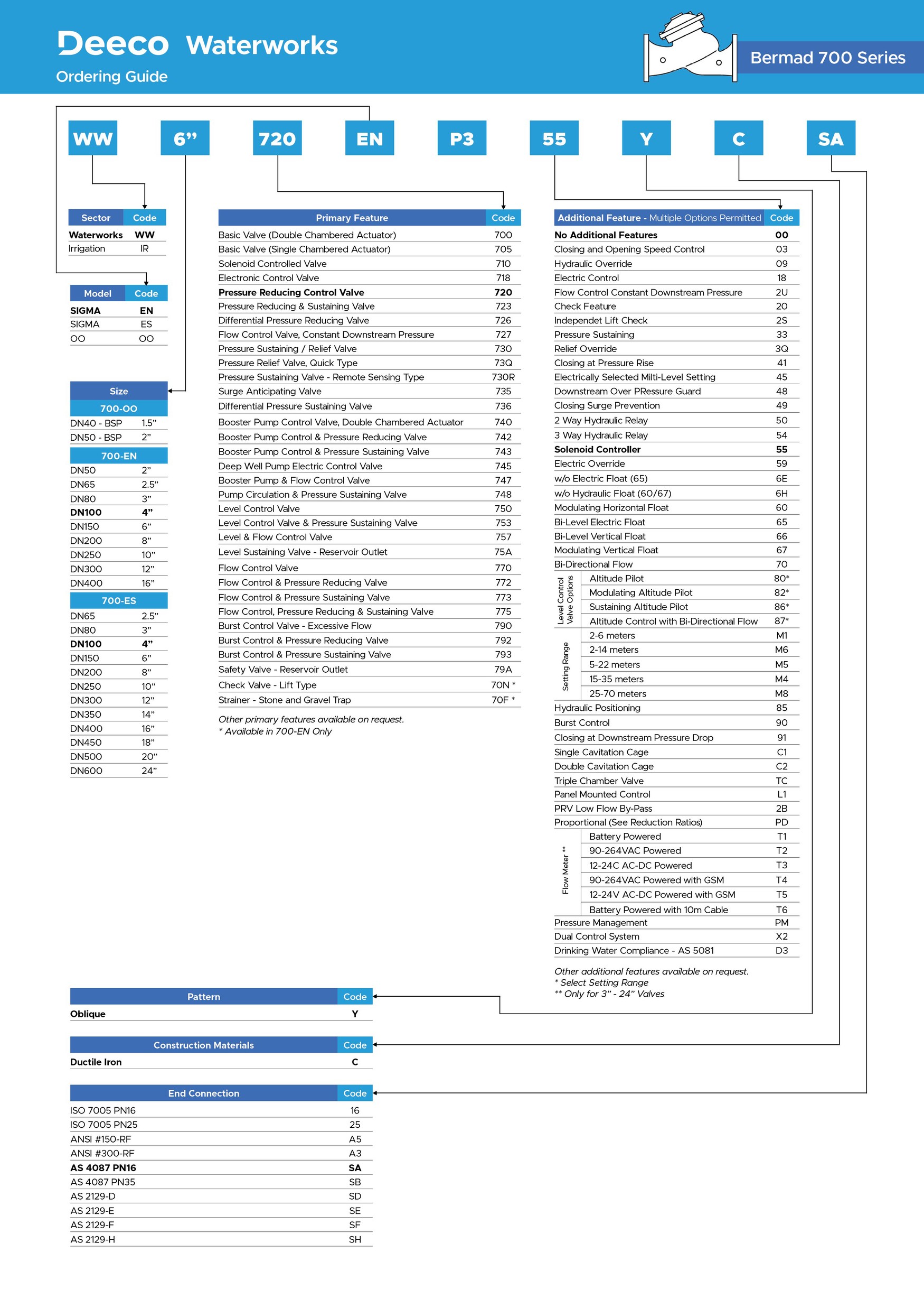
Product Description
The Model 735-M Surge Anticipating Valve is an off-line, hydraulically operated, diaphragm-actuated valve. Sensing line pressure, the valve opens in response to the pressure drop associated with abrupt pump stoppage. The pre-opened valve dissipates the returning high-pressure wave, eliminating the surge.
The Model 735-M smoothly closes drip tight as quickly as the relief allows, while preventing closing surge. The valve also relieves excessive system pressure.
- Eliminates surge in all pumping systems
- Booster & deep well, single & variable speed
- Eliminates surge in all distribution networks
- Municipal, high-rise buildings, sewage, HVAC, irrigation
- Difficult to maintain, remote locations, and older systems
Features and Benefits
- Replaces surge air vessels
- Relieves surge, fail-safe open
- Minimal maintenance
- Economy of space
- Lower investment & maintenance costs
- Especially economic for higher pressure ratings
- Line pressure driven
- Independent operation
- No motor required
- Long-term drip-tight sealing
- Adjustable hydraulic actuation
- Double chamber
- Moderated valve closing (no surges
- Protected diaphragm
- In-line serviceable – Easy maintenance
- Obstacle-free, full bore – Uncompromising reliability
- Balanced seal disk – High flow capacity
Major Additional Features
- Solenoid control – 735-55-M
- Sensing diaphragm (for sewage) – 735-Md
- Electric override for fire protection – FP-730-59
- Quick pressure relief valve – 73Q
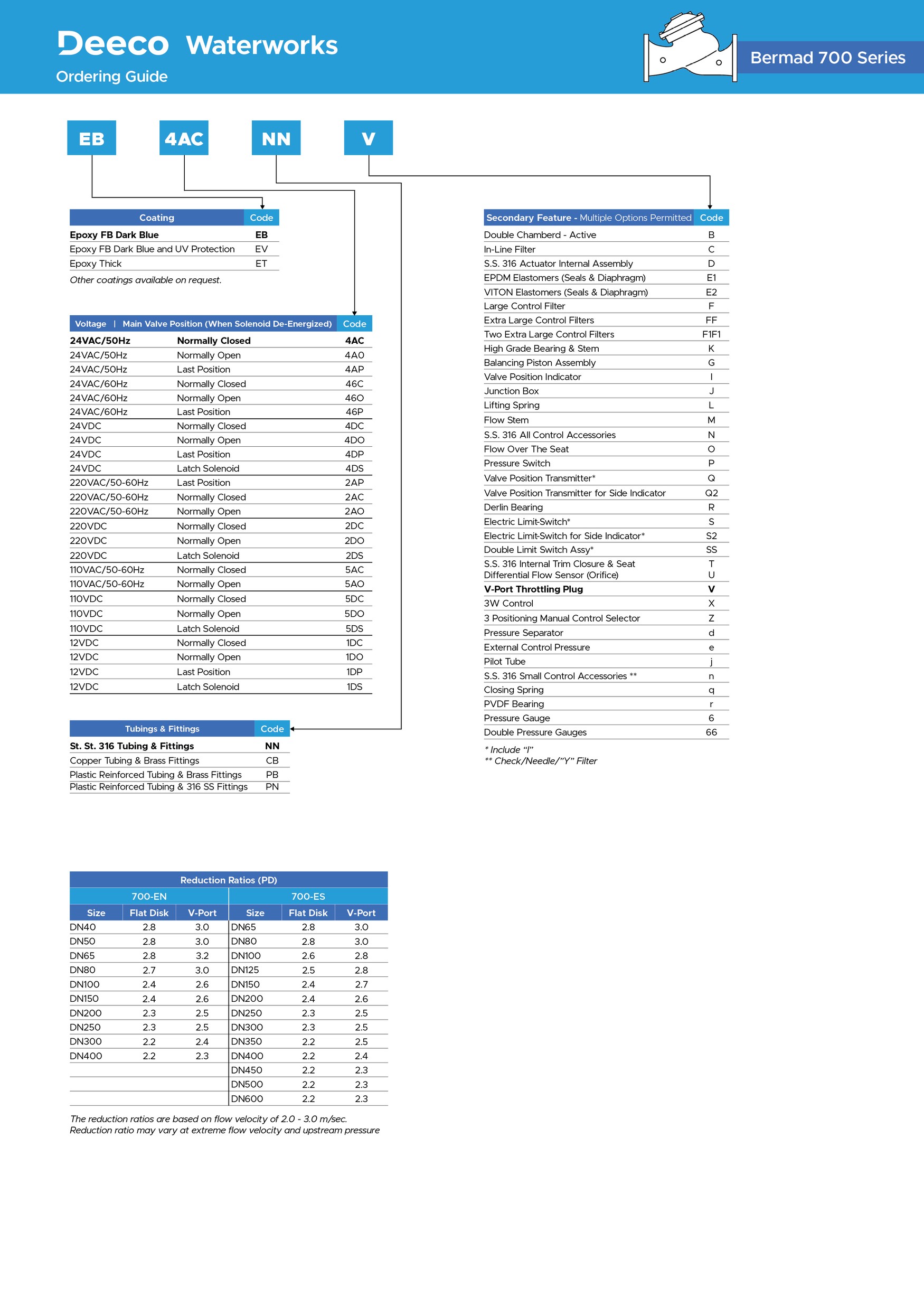
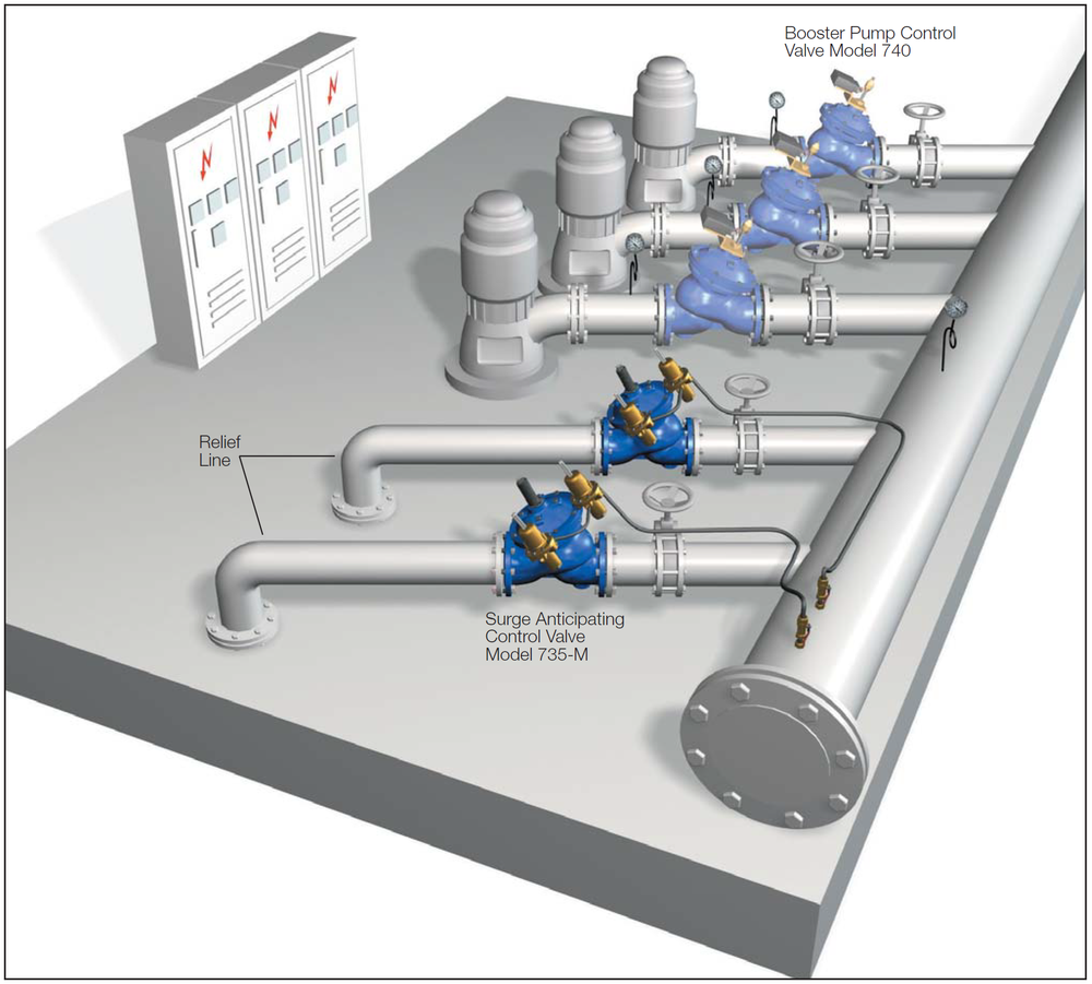
Typical Applications
A pump battery supplies the main line through a manifold in this system. The Model 735-M:
- Eliminates surge upon power failure
- Provides surge-free switching between “on-duty” pumps
- Closes smoothly according to pilot setting
Note:
Surge analysis assumes free flow through the Relief Line. Valve sizing and configuration should be reconsidered if the Relief Line is pressurized.
Technical Data
Operation
The abrupt stopping of a pump produces a pressure drop as the traveling column of water, with its inherent momentum, continues to travel along the line, generating severe low pressure. When the traveling column of water loses its momentum, it travels back towards the pump. Should it hit the closed check valve, a very high pressure surge is created and travels throughout the system as a damaging wave at velocities of up to "Mach 4". No quick relief valve can react quickly enough to eliminate it.
Surge at Pump Station Without Protection
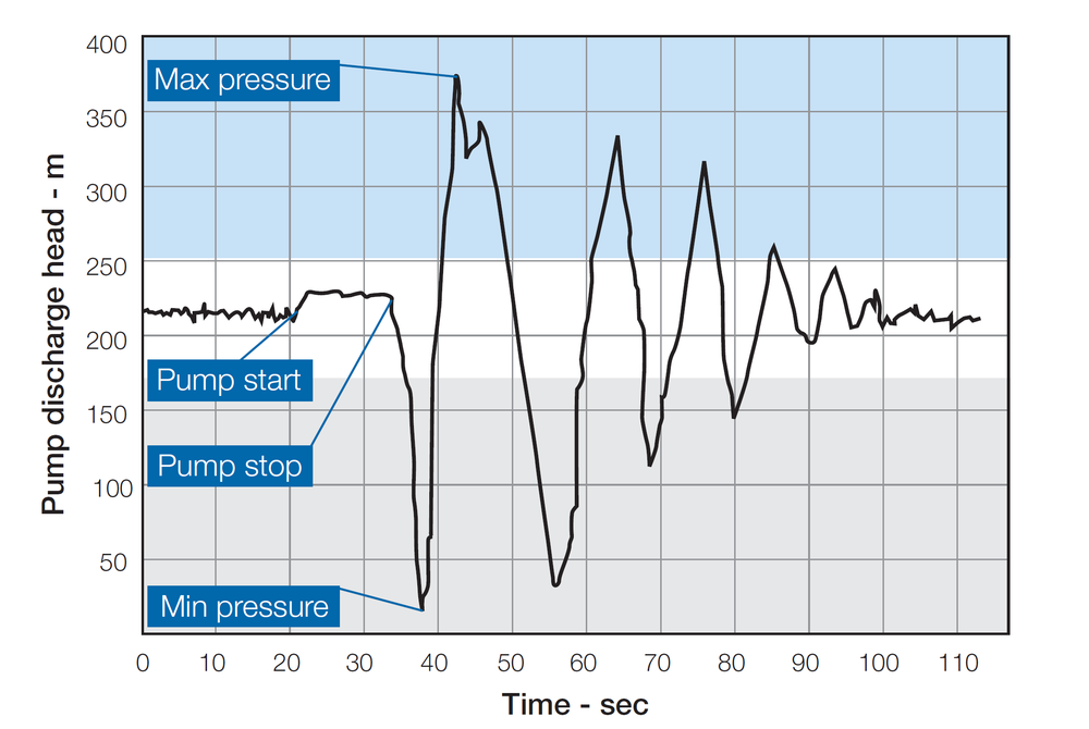
Bermad - 734 - Surge at Pump Station Without Protection
Eliminating surge requires anticipation and pre-action. The Model 735-M is well suited to this task.
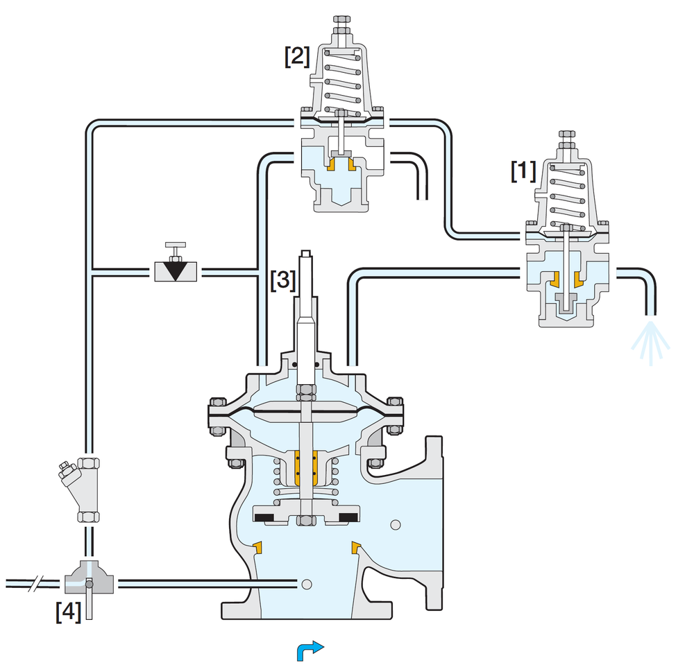
The Low Pressure (LP) pilot [1] senses the initial pressure drop and opens. This immediate reaction allows the remaining line pressure to quickly open the main valve.
The already opened Model 735-M releases the returning column of water, minimizing the line pressure rise. Should the relief rate be insufficient, and the pressure exceeds the High Pressure (HP) pilot [2] setting, the pilot immediately opens, further opening the main valve.
As system pressure stabilizes again at static pressure, both pilots close and the main valve begins closing. Should line pressure rise during the main valve closing, the HP pilot briefly stops the process, preventing the pressure from continuing to rise.
The flow stems [3] limit the relief flow to prevent column separation and preserve closing pressure.
Cock valve [4] serves for selecting operating and sensing sources:
■ Directly from main discharge line - Recommended (see “Typical Application”)
■ From Model 735-M inlet
Pressure at Pump Station Protected by Model 735-M
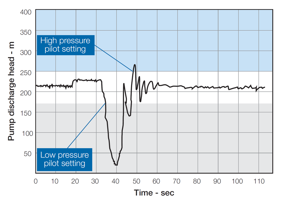
Bermad - Model 735 - Pressure at Pump Station Protected by 735-M
Bermad Surge Analysis Program – “BERSAP II”
Surge is the result of many factors: designed flow rate, pumping system, mainline characteristics, etc. By using advanced mathematics and computer software, BERMAD’s experienced engineers can perform the desired analysis.
For best analysis, all of the following data is required.
- Main Line
- Line Profile (Chainage), elevations at accumulated length
- Internal diameter
- Length
- Material
- Wall thickness
- Pumps
- Pump curve(s)
- Max. number of pumps in simultaneous operation
- Type of non-return valve
- System
- Max. designed flow rate
- Max. & min. levels at suction and at delivery reservoirs
For systems with multiple pumping stations and/or multiple consumers along the supply line, the following data is also required
- System layout including a pumping station, consumer locations, and characteristics
- Head Gradient Line (HGL) for each and every node based on “Network-Solver” analysis
Line Hydraulic Behavior without Protection
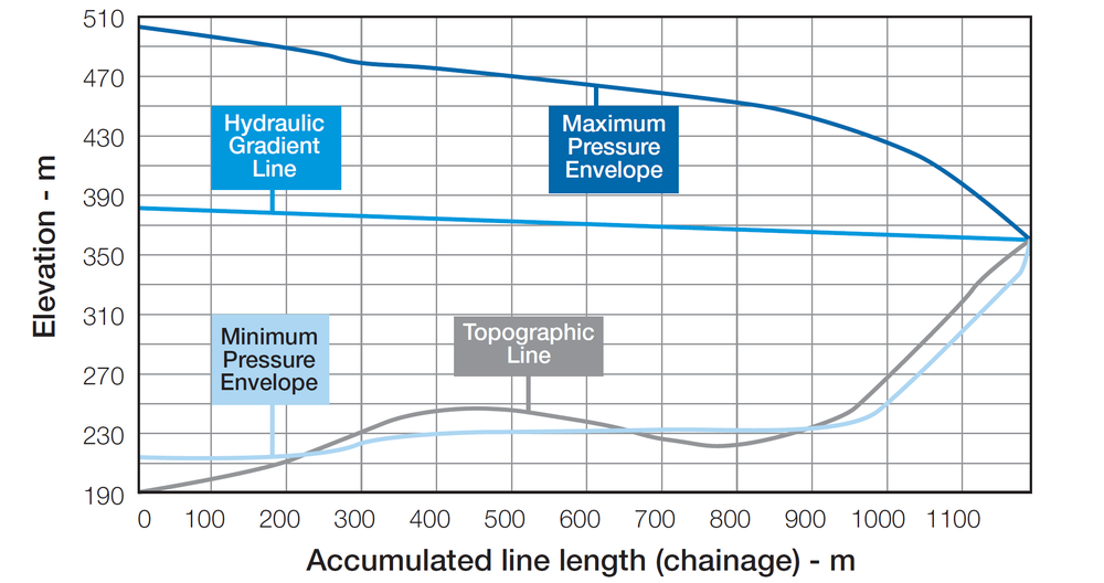
This surge analysis indicates that without protection the system is exposed to:
■ Pressure of ~32 bar
(see max. pressure envelope line)
■ Vacuum conditions
(see min. pressure envelope line)
Line Hydraulic Behavior with Full Protection
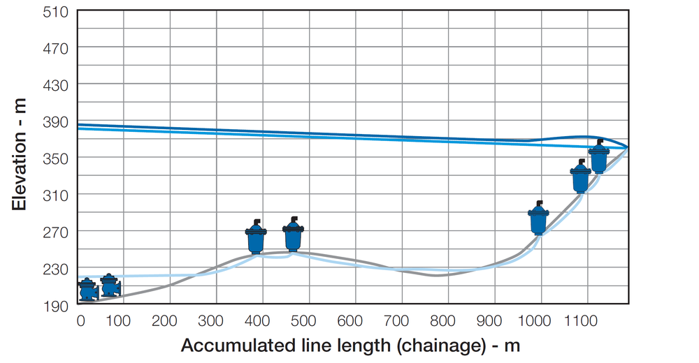
Simulated surge protection recommends:
■ Two Model 735-M valves installed in parallel at the pumping station
■ Five Non-Slam Air Valves installed along the line With full surge protection, the simulation shows no surge and minimal vacuum.
■ Pressure at max. of ~19 bar
(see max. pressure envelope line)
■ No appreciable vacuum
(see min. pressure envelope line)
Any pipeline design requires air valves to admit air under vacuum conditions and to release air under pressure. The size, type and location of these air valves should consider surge protection requirements.
Engineer Specifications
The Surge Anticipating Valve shall open in response to the pressure drop associated with abrupt pump stoppage to dissipate the returning high-pressure wave, eliminating the surge. It shall smoothly close drip tight as quickly as the relief feature allows while preventing a closing surge. The valve shall also relieve excessive system pressure.
Main Valve: The main valve shall be a center-guided, diaphragm-actuated globe valve of either oblique (Y) or angle pattern design. The body shall have a replaceable, raised, stainless steel seat ring. The valve shall have an unobstructed flow path, with no stem guides, bearings, or supporting ribs. The body and cover shall be ductile iron. All external bolts, nuts, and studs shall be Duplex® coated. All valve components shall be accessible and serviceable without removing the valve from the pipeline.
Actuator: The actuator assembly shall be double-chambered with an inherent separating partition between the lower surface of the diaphragm and the main valve. The entire actuator assembly (seal disk to top cover) shall be removable from the valve as an integral unit. The stainless steel valve shaft shall be center guided by a bearing in the separating partition. The replaceable radial seal disk shall include a resilient seal and shall be capable of accepting a V-Port Throttling Plug by bolting.
Control System: The control system shall consist of two adjustable 2-way pilots, a needle valve, a flow stem, a cock valve, and a filter. All fittings shall be forged brass or stainless steel. The assembled valve shall be hydraulically tested.
Quality Assurance: The valve manufacturer shall be certified according to the ISO 9001 Quality Assurance Standard. The main valve shall be certified as a complete drinking water valve according to NSF, WRAS, and other recognized standards.
Main Valve
Valve Patterns: “Y” (globe) & angle
Size Range: 50-600mm
End Connections:
EN: 50-400mm - Flanged
ES: 65-600mm - Flanged
Others: Available on request
Working Temperature: Water up to 60°C
Standard Materials:
Body & Actuator: Ductile Iron
Internals: Stainless Steel, Bronze & coated Steel
Diaphragm: NBR Nylon fabric-reinforced
Seals: NBR
Coating: Fusion Bonded Epoxy, RAL 5005 (Blue)
NSF & WRAS approved or Electrostatic
Polyester Powder, RAL 6017 (Green)
Control System
Standard Materials:
Accessories: Bronze, Brass, Stainless Steel & NBR
Tubing: Copper or Stainless Steel
Fittings: Forged Brass or Stainless Steel
Pilot Standard Materials:
Body: Brass, Bronze or Stainless Steel
Elastomers: NBR
Springs: Galvanized Steel or Stainless Steel
Internals: Stainless Steel
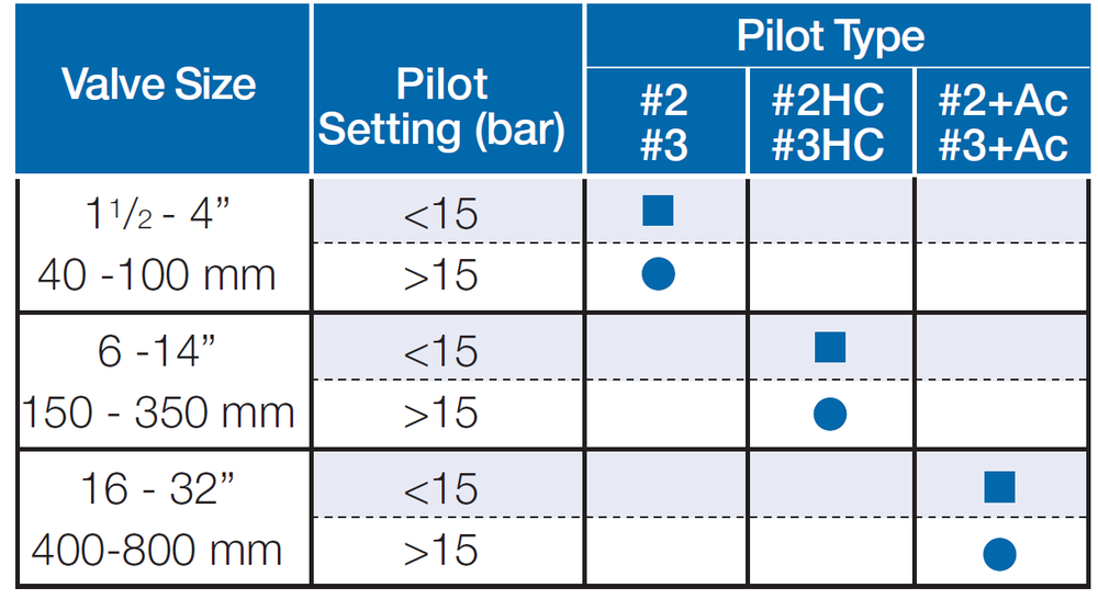
■ Standard model ● with high-pressure setting kit
Ac-Accelerated Opening valve
Technical Specifications
For technical specifications (Flow charts, valve characteristics, dimensions, etc.) - Please refer to the Engineering Data:
Bermad - Model 700 - Sigma EN/ES - Engineering Data
For Spare Parts & Repair Kits - Please refer to the base model:
Due to the wide range of options available and criteria for correct model selection, pricing and configuration are available on application only.
Please consult with Deeco engineers for more information.