| Brand: | Bermad |
| Category: | Control Valves, 800 Series |
| Connection: | Flanged |
| Size Range: | 40-500mm |
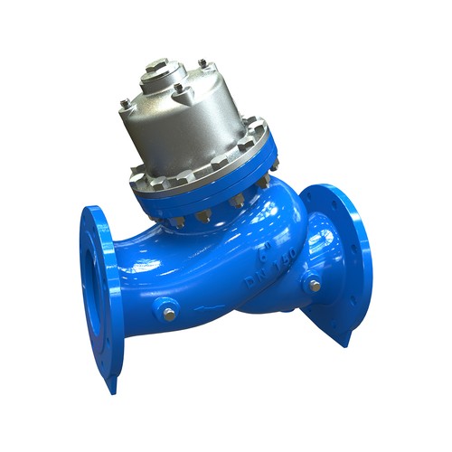
Product Description
BERMAD 800 series valves are hydraulically operated control valves, designed for high-pressure operation and available in either standard oblique pattern with high cavitation resistance, excellent flow capacity, or angle pattern design. Their double-chamber unitized piston actuator can be disassembled from the body as a separate integral unit. The valve hydrodynamic body is designed for an unobstructed flow path and provides excellent and highly effective modulation capacity for high differential pressure applications, with minimal noise and vibrations. The 800 series meets all flange connection standards.
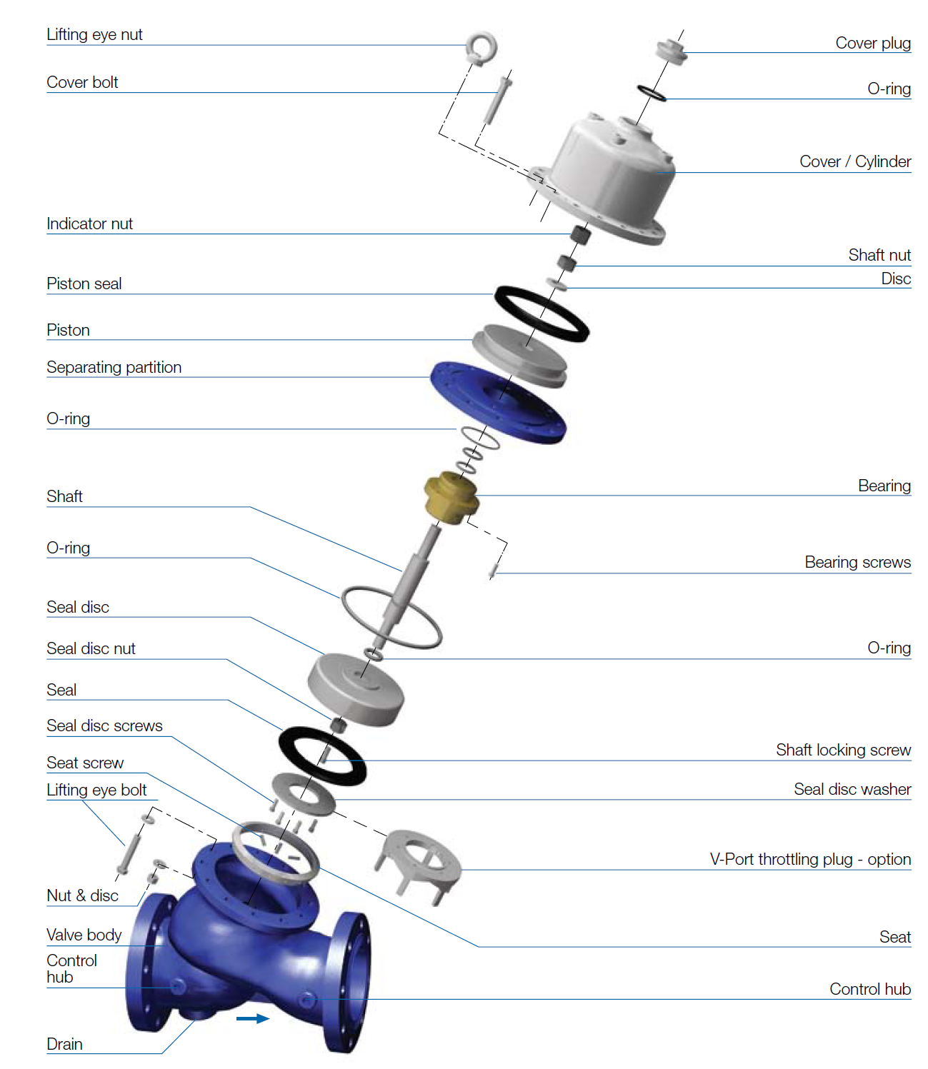
Exploded View
Technical Data
Series Patterns and Sizes
- 800 Series - "Y" Pattern - DN40-500
Connection Standard
- Fֺֺlanged: ISO 7 005-1(ISO 10, 16, 25 & 40)
Water Temperature
- Uֺֺp to 80ºC
Working pressure
- ISO PN 16: 16 bar
- ISO PN 25: bar
- ISO PN 40: 40 bar
Standard Materials
Main valve body
- Carbon Steel to EN 10083-1
Valve cover (piston cylinder)
- Stainless Steel or Bronze
Main valve internals
- Stainless Steel and Bronze
Control Trim
- Brass, Bronze accessories
- Stainless Steel 316 fittings & tubing
- or forged Brass fittings & copper tubing
Elastomers
- NBR
Coating
- Blue Fusion bonded Epoxy
Optional Materials
Main Valve Body and Cover
- Ductile Iron to EN 1563
- Stainless Steel 316 to EN 10088-1
- Nickel Aluminum Bronze to BS-EN 1400 AB-2
- Other materials on request
Control Trim
- Stainless Steel 316, Nickel Aluminum Bronze,
- Hastalloy C-276 accessories
- Monel fittings & tubing
Elastomers
- EPDM
- FPM
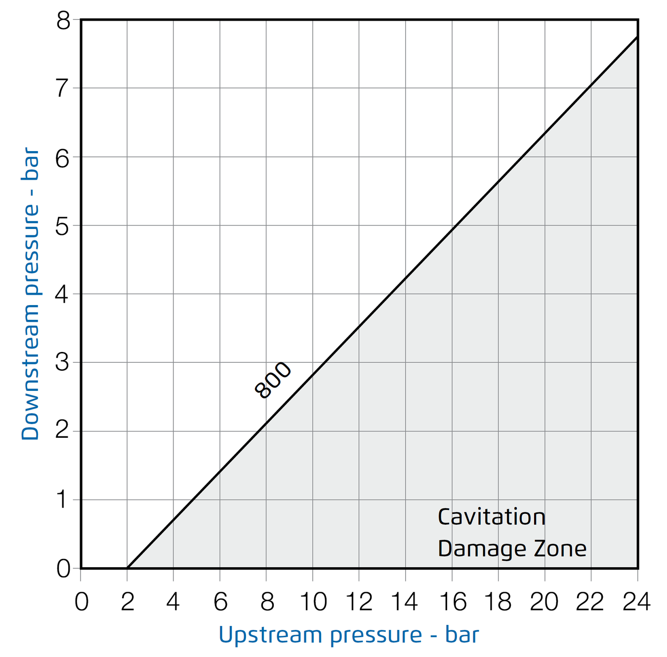
Cavitation
The cavitation phenomenon has a significant effect on the control valve and system performance. Cavitation may damage the valve and piping by the effects of erosion and vibration. Cavitation also generates noise and may limit and ultimately choke the flow. As the pressure differential across the valve increases, the static pressure of the flow passing through the throttling area of the valve (Vena Contract) drops sharply. When the fluid’s static pressure reaches liquid vapor pressure, vapor cavities (bubbles) form and grow until they violently implode by the recovered pressure downstream to the valve seat. The implosion of these cavities generates high-pressure surges, microjets, and intensive heat, which erode valve components and downstream piping. In its final stage, cavitation flashes and chokes the flow. The above Cavitation Guides for Bermad 7 00 Series valves are based on the formula commonly used in the valve industry:
σ = (P2-Pv) / (P1-P2)
Where:
σ = Sigma, cavitation index, dimensionless
P1 = Upstream pressure, absolute
P2 = Downstream pressure, absolute
Pv = Liquid vapor pressure, absolute
(Water, 18ºC = 0.02 bar-a ; 65ºF = 0.3 psi-a)
Use these guides and your applications upstream and downstream pressures to determine whether their intersection lies in or out of the cavitation damage zone.
Considerations to avoid cavitation damage:
A) Reduce system pressure in stages designing each pressure stage to be above cavitation conditions.
B) Consider using other valve selection criteria
Notes:
- An alternate cavitation index formula introduced by ISA is:
σISA = (P1-Pv) / (P1-P2) which equals σ+1
- The above charts should be considered only as a
general guide.
- For optimum system and control valve application, Please contact Deeco.
Cavitation Guide
Technical Specifications
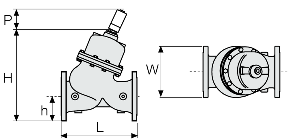
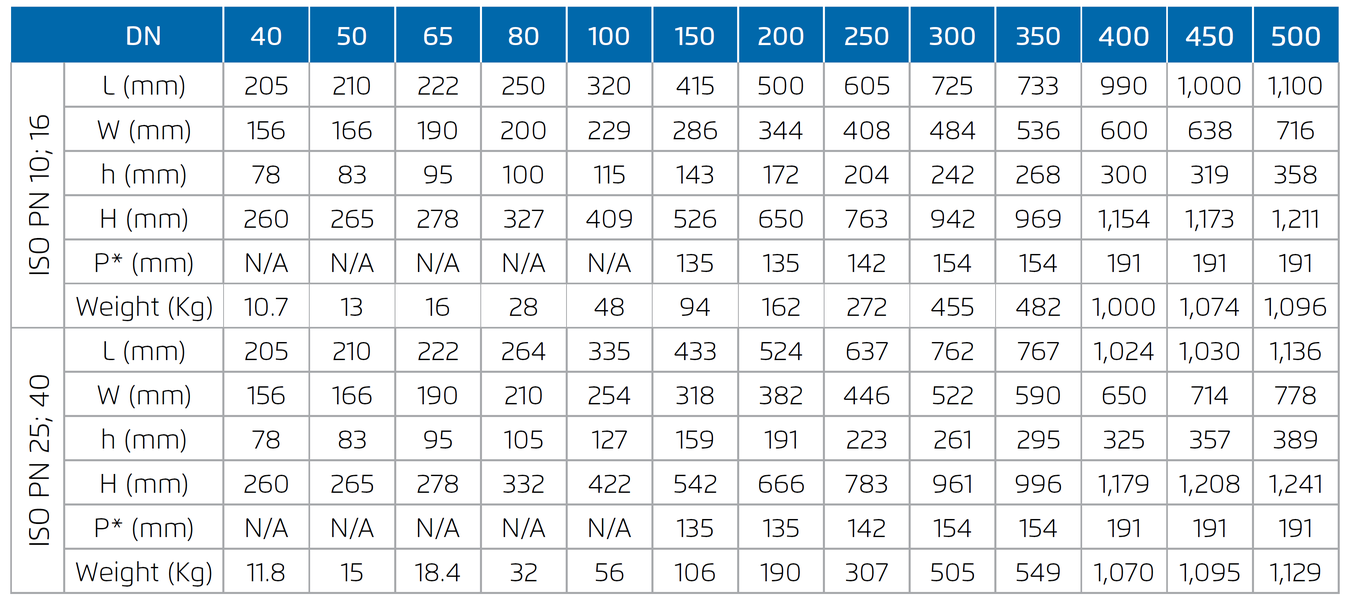
Dimensions and Weights
Control Chamber Displacement Volume (liter)

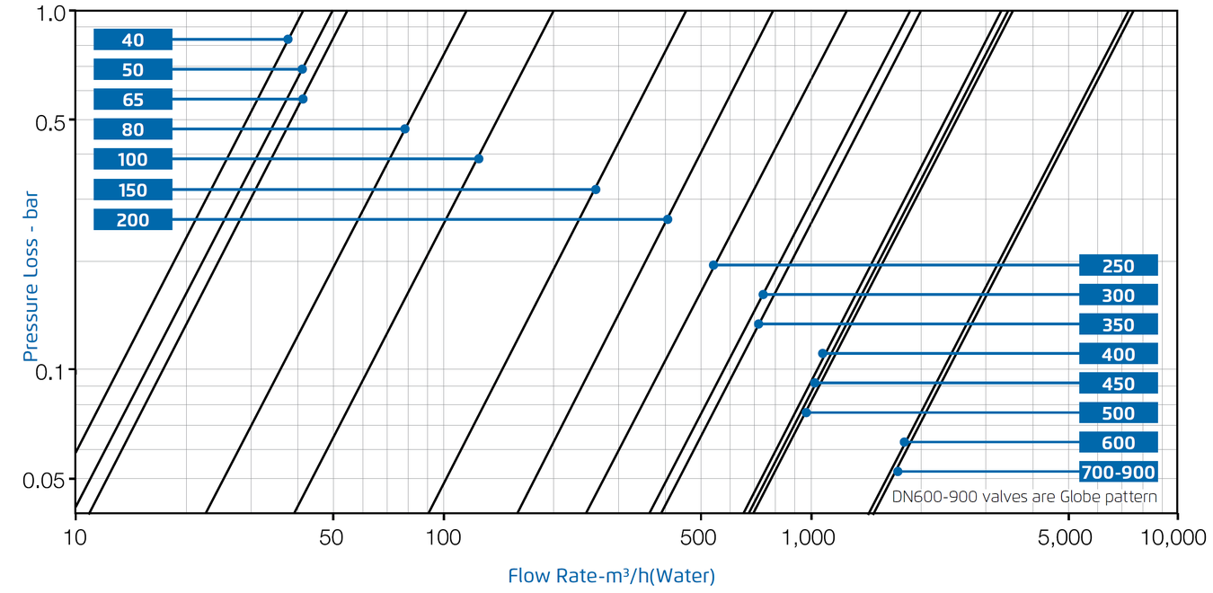
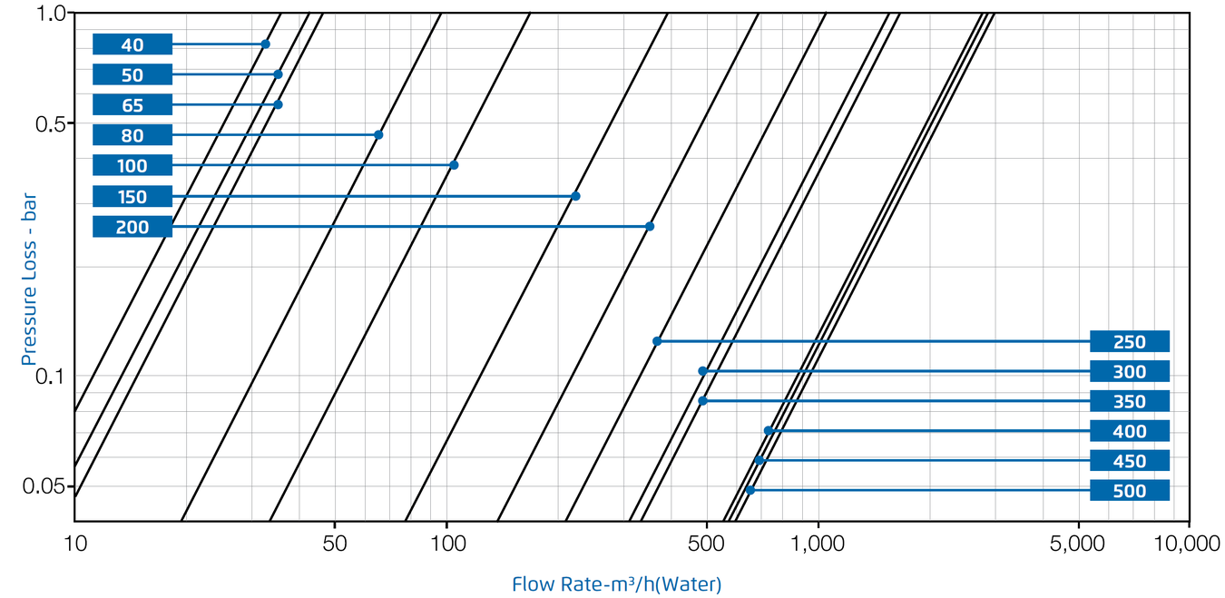
Flow Charts
Y Pattern, Flat Disc
Y Pattern, Throttling Plug (V-Port)
Flow Properties
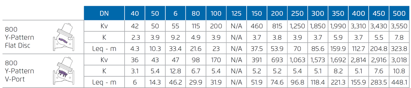
Differential Pressure Calculation
Valve flow coefficient, Kv or Cv
Kv (Cv) = Q √Gf/ ∆P where:
Kv = Valve flow coefficient (flow in m3/h at 1bar ΔP)
Cv = Valve flow coefficient (flow in gpm at 1psi ΔP)
(Cv = 1.155 Kv)
Q = Flow rate (m3/h ; gpm)
ΔP = Differential pressure (bar ; psi)
Gf = Liquid specific gravity (Water = 1.0)
Practical formulas for water:
Q= Kv√ΔP
ΔP= (Q/Kv)²
Flow Resistance or head loss coefficient, K= ΔH (2g/v²) where:
K = Flow resistance or Head loss coefficient (dimensionless)
ΔH = Head loss (m ; feet)
V = Nominal size flow velocity (m/sec ; feet/sec.)
g = Acceleration of gravity (9.81 m/sec2 ; 32.18 feet/sec2)
Practical formula:
ΔH= K (V²/2g)
Equivalent Pipe Length - Leq
In order to simplify system head loss calculation, add the Leq value to the pipe length of the relevant size
Note:
The Leq values given are for general consideration only. Actual Leq may vary somewhat with each of the valve sizes.
Due to the wide range of options available and criteria for correct model selection, pricing and configuration are available on application only.
Please consult with Deeco engineers for more information.