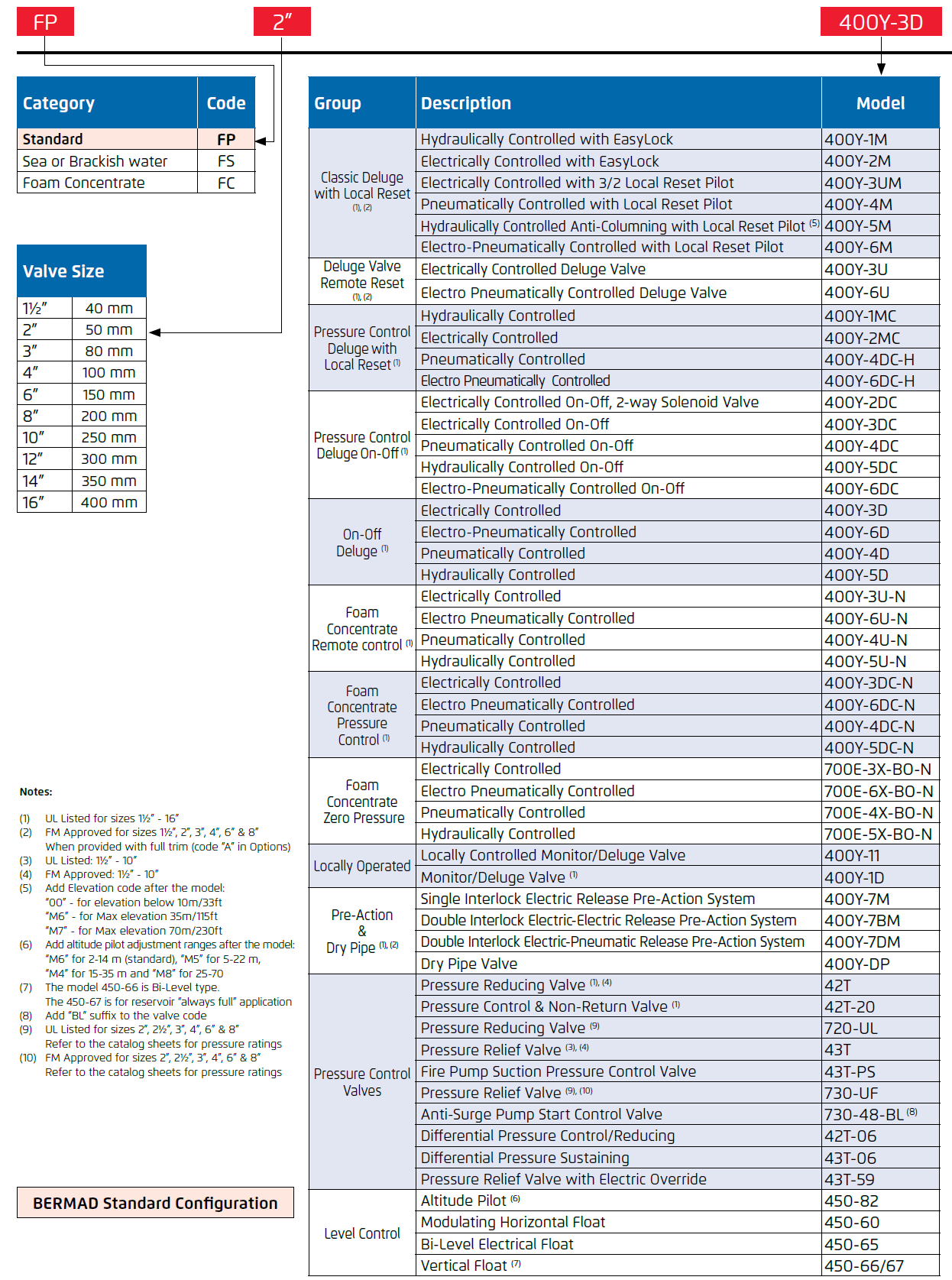
| Brand: | Bermad |
| Category: | Control Valves, Fire Protection Series |
| Size and Range: | 50-400mm |
| Connection: | 50 - 400mm - Flanged 80 - 200mm - Grooved |
| Engineering Data: |
Product Description
The BERMAD Model FP 730-UF pilot-operated relief valve prevents overpressure, maintaining a constant preset system pressure regardless of fluctuating conditions. It is UL-Listed (up to 350 psi) and FM-Approved in accordance with NFPA-20. The valve offers reliable performance when installed in Refineries, petrochemical complexes, tank farms, high-rise buildings, aviation and airports, marine and onshore installations.
Features and Benefits
- Hydraulically powered valve seal design
- Reliable drip-tight sealing
- Eliminates jamming problems.
- Hydro-efficient body design
- Wide operating range
- An Unobstructed straight-through flow path
- Double-chambered unitized actuator
- An Easy, inline inspection ensures minimal downtime.
- Quick and smooth valve action
Optional Features
- Large control filter (code: F)
- Seawater service construction
Note: Optional features can be mixed and matched. Consult your local BERMAD representative for full details.
Approvals
- UL Listed - Fire Pump Relief Valve (QXZQ)
- FM Approved - Water Relief Valve and Fire Pump Relief Valve
- ISO 9001 QA certified
- ABS - Type Approved
- Lloyd’s Register - Type Approved
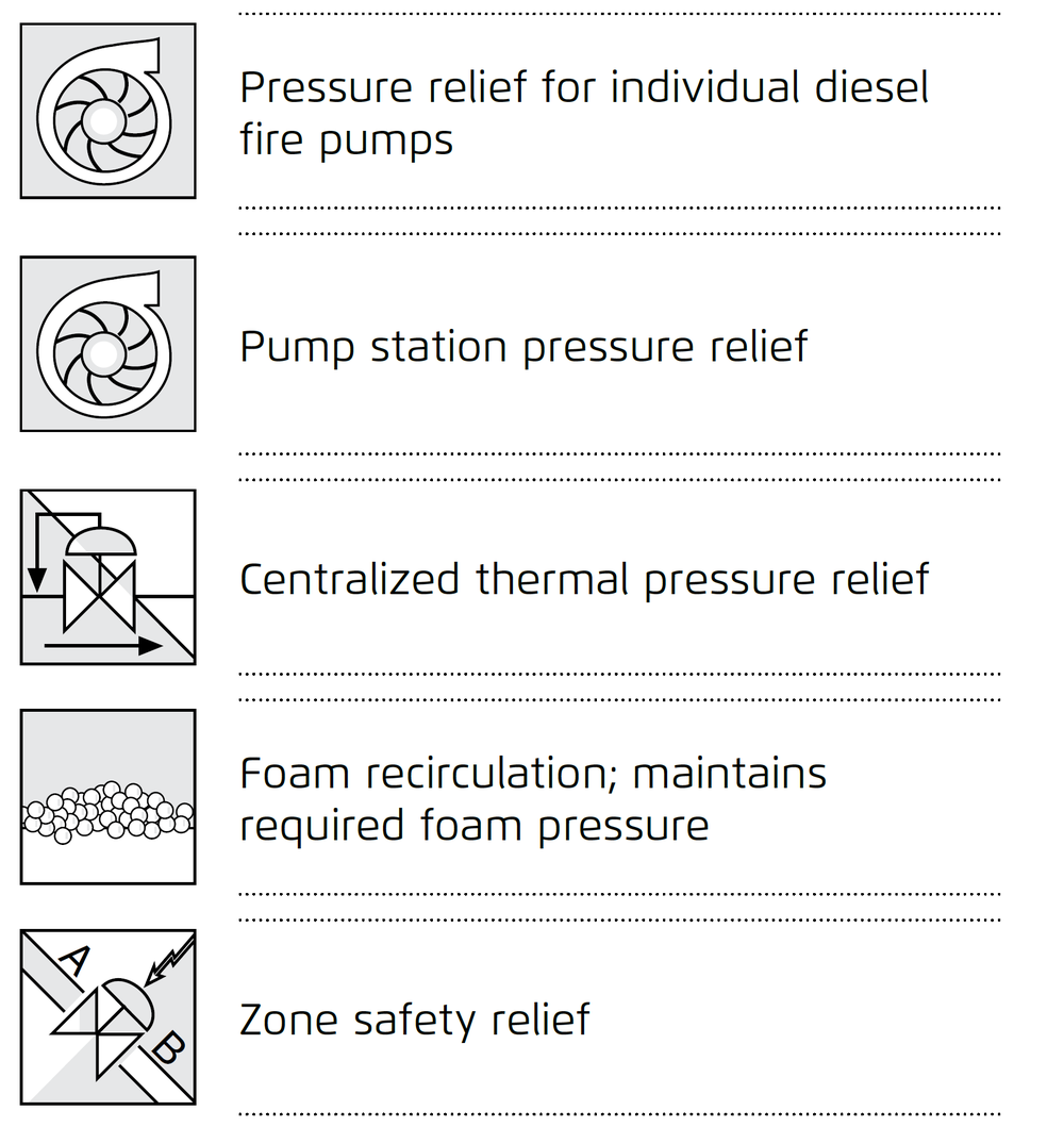
Typical Applications
Technical Data
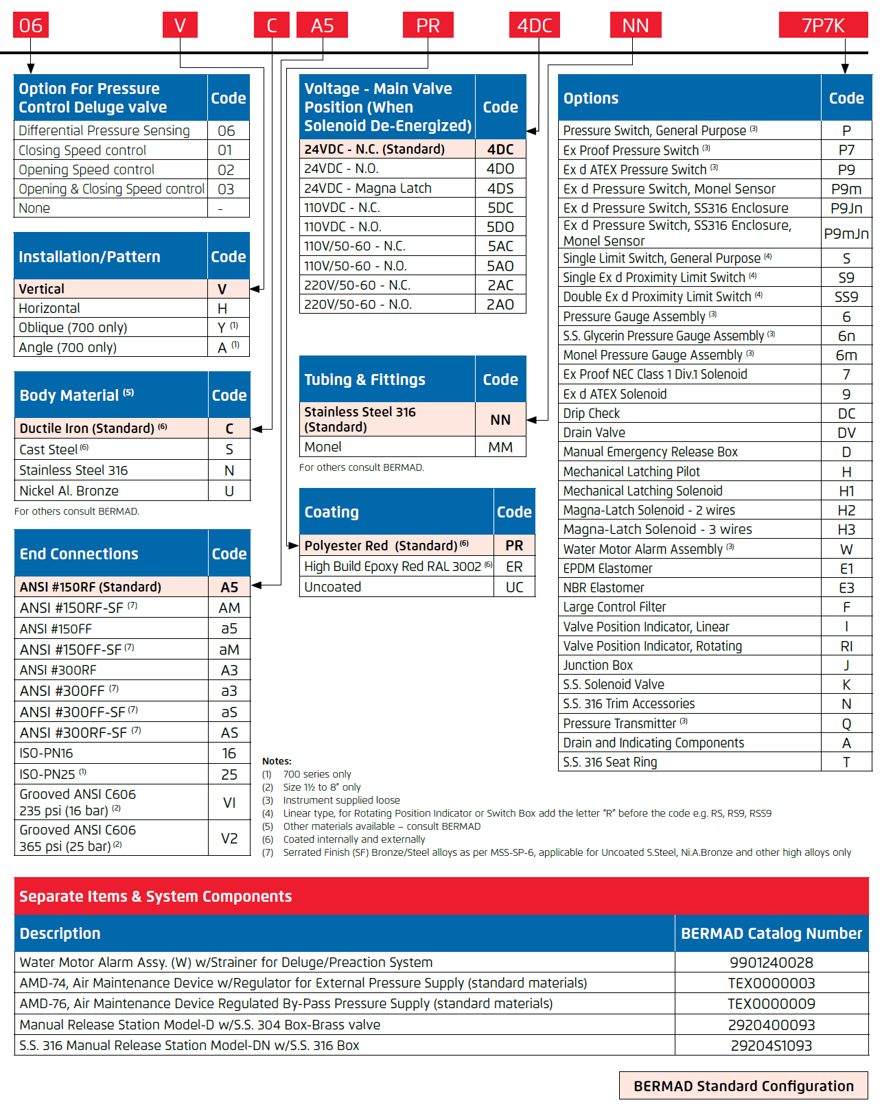
Operation
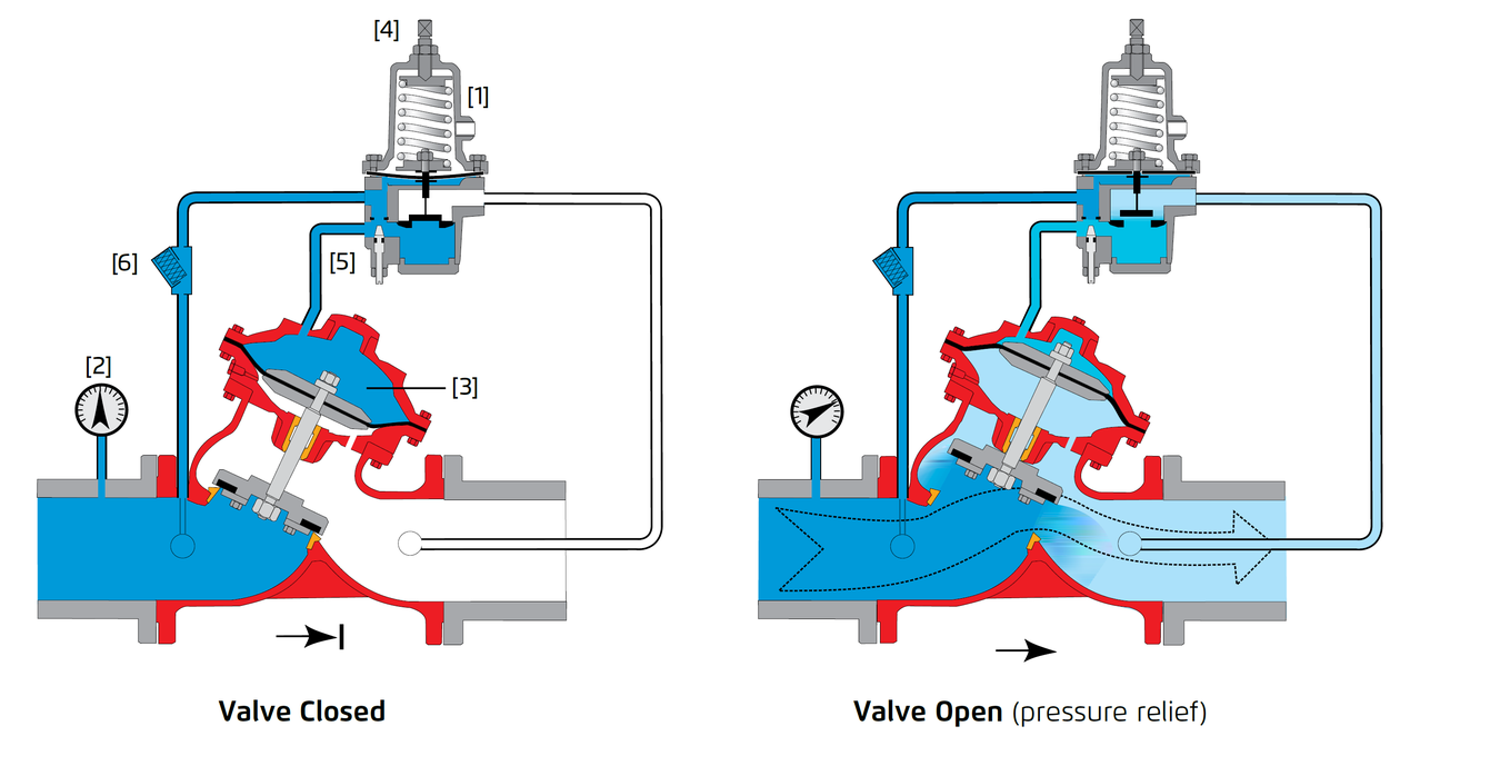
The BERMAD Model FP 730-UF remains closed as long as the sensed inlet pressure is lower than the adjustable set point. When the Pressure Relief Pilot [1] senses inlet pressure [2] that is higher than the pilot setting, it opens releasing water pressure from the control chamber [3] and causing the main valve to modulate open, relieving excess pressure to either a reservoir or sump, preventing system overpressure. The Pressure Relief Pilot is equipped with an adjusting screw [4] to preset the desired inlet pressure and an integral adjustable needle valve [5] to control the main valve closing speed. The valve’s unique design and quick reaction to system demand keep pressure loss at a minimum. To further enhance reliability the control system is equipped with a control strainer [6].
Manufacturers Standard Materials
Main valve body and cover
- Ductile Iron ASTM A-536
Main valve internals
- Stainless Steel, Bronze and coated Steel
Control Trim System
- Brass control components/accessories
- Forged Brass fittings & Copper tubing
Elastomers
- NBR (Buna-N)
Coating
- Electrostatic Powder Coating Polyester, Red (RAL 3002)
Optional Materials
Main Valve Body/Internals
- Carbon Steel ASTM A-216-WCB
- Stainless Steel 316
- Ni-Al-Bronze ASTM B-148
- Titanium
- Duplex
- Hastalloy
Control Trim
- Stainless Steel 316
- Monel® and Al-Bronze
- Hastalloy C-276
Coating
- High Build Epoxy Fusion-Bonded with UV Protection, Anti-Corrosion
Main Valve
Connection Standard
- Flanged: ANSI B16.42 (Ductile Iron), B16.5 (Steel & Stainless Steel), B16.24 (Bronze), ISO PN16
- Threaded: NPT or ISO-7-Rp 2, 2½ & 3”
- Grooved: ANSI/AWWA C606 for 2, 3, 4, 6 & 8”
Water Temperature
- 0.5 - 80°C (33 - 180°F)
Sizes (“Y” & Angle)
- Available Y: 1½ - 20”, Angle: 1½ – 18”
- UL Listed and FM approved: 2, 2½, 3, 4, 6 & 8”
Pressure Rating
- UL Listed - 2 to 6”: 350 psi (24 bar)
8”: 175 psi (12 bar) - ANSI#150 235 psi/16 bar (code A5)
- ANSI#300 350/24 bar (code A3)
- ISO 16 235 psi/16 bar (code 16)
- ISO 25 350/24 bar (code 25)
- Grooved 235psi/PN16, ANSI C606 (code V1)
- Grooved 365psi/PN25, ANSI C606 (code V2)
Pressure Settings Range
- Class #150: 30 – 235 psi (2 – 16 bar)
- Class #300: 100 – 350 psi (7 – 24 bar)
Technical Specifications
For more technical specifications (Flow charts, valve characteristics, dimensions, etc.) - Please refer to the Engineering Data:
Engineer Specifications
The Pressure Relief Valve shall be UL-Listed, FM-Approved and hydraulic pilot controlled. The main valve shall be an angle or “Y” pattern. All necessary inspections and servicing of the main valve shall be possible in-line. Valve actuation shall be accomplished by a double-chambered actuator, which shall include a stainless steel stem and a flat seal disk creating a drip-tight seal. The valve seat shall be made of stainless steel and have an unobstructed flow path, with no stem guide or supporting ribs. The pilot system shall be field adjustable, with adjustable valve closing speed, integrated into the pilot valve, hydraulically tested and supplied as an assembly consisting of:
- Relief pilot valve UL-Listed and FM-Approved as part of the assembly with built-in, internal needle valve
- “Y” strainer
The control trim shall be supplied as an assembly, pre-assembled and hydraulically tested at an ISO 9000 and 9001-certified factory.
Typical Installation
System Components
- BERMAD Model FP 730-UF
- Fire Pump
- Check Valve
- Pressure Gauge
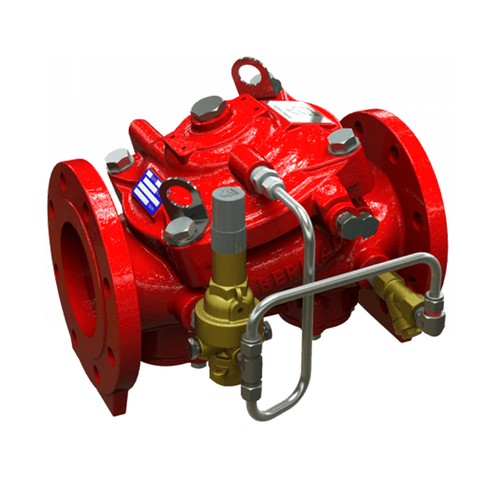
Installation with Angle pressure Relief Valve
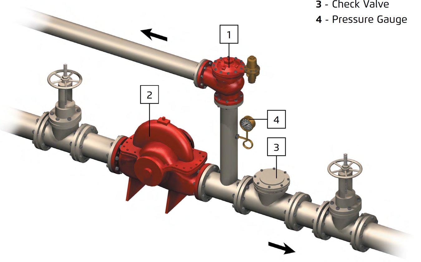
Bermad - FP-730 - Installation with Angle Pressure Relief Valve
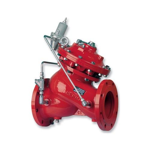
Installation with “Y” Pattern relief valve
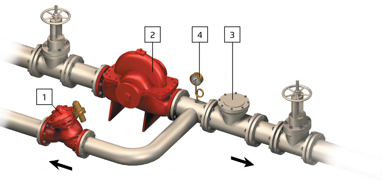
Bermad - FP-730 - Installation With Y Pattern Relief Valve
Installation Considerations
- Valve size should be no less than NFPA-20 requirements.
- Provide adequate clearance around the valve for maintenance, ensuring that the actuator can be easily removed.
- Design installation with the valve cover-up for best performance.
- Ensure that before the valve is installed, instructions are given to flush the pipeline at full flow.
UL Listed
The BERMAD Model FP 730-UF is UL-Listed and FM-Approved when installed as a unit.
Dimensions and Weights
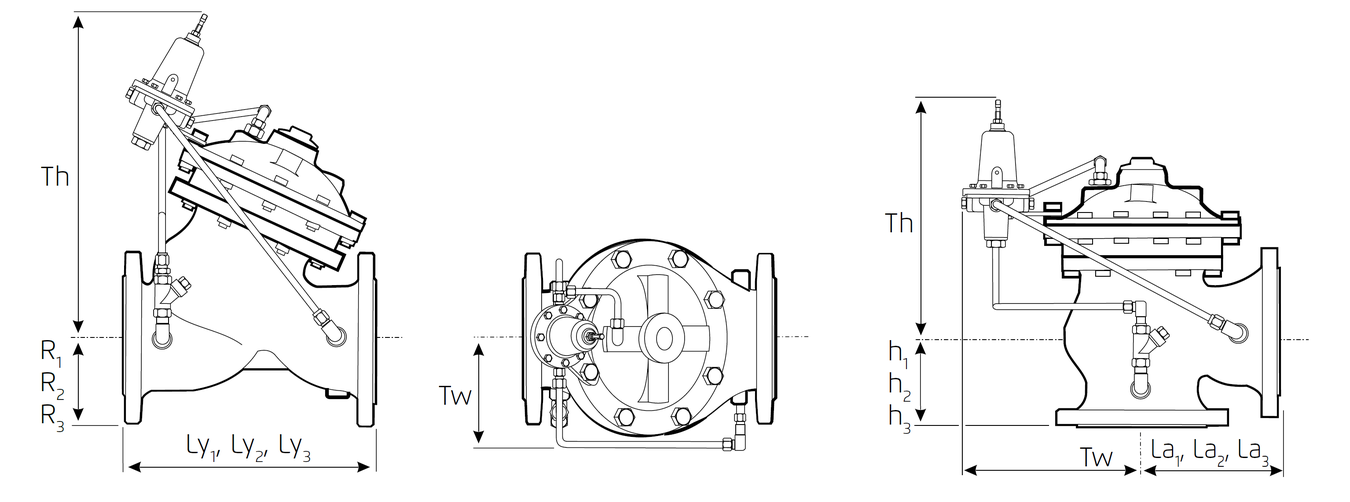
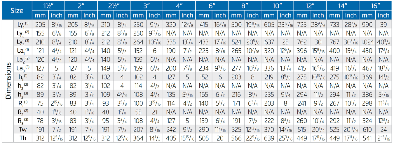
1. Ly1 for ANSI#150, ISO PN16 & Grooved ends (see available sizes below)
2. La1 & h1 for Angle body, ANSI#150 and ISO PN16.
3. Ly2, La2 & h2 for threaded female, NPT or BSP.
4. Ly3, La3 & h3 for flanged ANSI #300 and ISO PN25
5. Data is for maximum envelope dimensions, component positioning may vary
6. Provide adequate space around the valve for maintenance.
Due to the wide range of options and criteria for correct model selection, pricing and configuration are available on application only.
Please contact us for more information.